ROMBUS: Reusable Orbital Module - Booster & Utility Shuttle (1963)

Engineer Philip Bono described his conceptual ROMBUS launch vehicle as a crew-carrying system, though he did not describe the crewed spacecraft it would launch. The image above displays a ROMBUS vehicle on its launch platform with a typical conical payload shroud. Image credit: Douglas Aircraft Company via San Diego Air & Space Museum.

As the 1960s decade began, NASA Marshall Space Flight Center (MSFC) had big ambitions. The Huntsville, Alabama-based facility, which left the U.S. Army to join NASA on 1 July 1960, aspired to build ever-more-powerful launch vehicles for the new U.S. space program. The Saturn family of rockets would, it was hoped, lead to the giant Nova booster, which might launch the first lunar landing mission and, eventually, lunar base hardware and spacecraft for crewed voyages to the planets.

Following President John F. Kennedy's 25 May 1961 call for a U.S. astronaut on the Moon by 1970, however, NASA selected the Saturn V rocket as its Apollo lunar landing mission workhorse. Interest in Nova outside NASA MSFC dwindled. This was bad news for the Huntsville rocketeers; if no Saturn successor was in development as Apollo reached the Moon, they might find themselves celebrating the first lunar landing with layoffs and facility closures.

NASA MSFC's response was to try to shape the civilian space program's course beyond Apollo. In May 1962, it hired three companies to carry out the EMPIRE study, which looked at 1970s crewed Mars/Venus flyby missions launched on "post-Saturn" rockets (see "More Information" below). The following month, it awarded contracts to study post-Saturn rockets with capabilities similar to those planned for Nova. The post-Saturn contracts called for designs of launch vehicles that could boost up to 500 U.S. tons/454 metric tons of payload to 200-mile-high/325-kilometer-high low-Earth orbit.

One of the post-Saturn rocket study contractors was Douglas Aircraft Company of Santa Monica, California. Douglas was no stranger to large rockets; the company had won the NASA contract to build the S-IVB rocket stage, the third stage of the Saturn V and the second stage of the Saturn IB, the Saturn V's smaller cousin.

Philip Bono headed up the 18-member post-Saturn rocket study team at Douglas. In June 1963, when he reported results of the first year of the study at the American Institute of Aeronautics and Astronautics (AIAA) Summer Meeting in Los Angeles, he was Chief Advanced Projects Engineer for Future Space Systems in the company's Missile & Space Systems Division Advanced Launch Technology Team

I have spotlighted Bono's imaginative concepts on this blog before (see "More Information" below). In 1960, while he worked for Boeing, he described a Mars expedition built around a scaled-up version of the Dyna-Soar space plane the company was developing for the U.S. Air Force. The heavy-lift rocket he designed to launch his Mars ship included plug-nozzle engines, about which more in a moment. In 1962, after he moved to Douglas, he proposed ROOST, a single-stage-to-orbit reusable launch vehicle. 

In addition to a clear view of the ROMBUS plug-nozzle engine (the turbopump exhaust port at the center of the plug and the ring of combustion chamber segments at the plug's edge are plainly visible), this view of the ROMBUS vehicle contains one inaccuracy and one (solved) mystery. The four landing legs should not be extended while the eight yellow liquid hydrogen tanks and the conical payload shroud remain attached to the centerbody. The large nozzles shown to the left of liquid hydrogen tank 7 and to the right of liquid hydrogen tank 3 are not discussed in written sources used in this post; they are, however, labeled in a blurry illustration (not in this post) as two of four solid-propellant rocket motors for thrust augmentation. Image credit: Douglas Aircraft Company via San Diego Air & Space Museum.

Four views of the ROMBUS launch vehicle. Upper left: bottom of the vehicle. Lower left: top of the vehicle. The center and right views are self explanatory. Image credit: U.S. Patent Office. 

The post-Saturn rocket Bono described to the AIAA, which he named ROMBUS, combined the plug-nozzle engine of his Mars expedition rocket with ROOST's single-stage-to-orbit design and reusability. Of these features, the plug-nozzle engine most defined the ROMBUS design.

The plug-nozzle rocket engine is a form of aerospike rocket engine. As its name suggests, in the typical 1960s aerospike engine a trailing cone or "spike" replaced the bell-shaped nozzle of the conventional rocket engine. In effect, as its proponents liked to say, the aerospike engine turned the bell-nozzle engine inside out.

Rocket plume size is governed in large part by ambient atmospheric pressure, which in turn is governed by altitude. At launch from Earth's surface, air pressure surrounding the plume is at its greatest. The bell-nozzle plume at launch is typically smaller than the inside of its engine bell, leading to plume instability, which in turn leads to reduced engine thrust. The plume increases in size to fill the bell as the rocket gains altitude and ambient pressure decreases, reducing instability and increasing thrust; in other words, bell-nozzle engine thrust increases toward optimum with increasing altitude. If the width of the plume should expand beyond the lip of the bell, however, instability recurs, again reducing thrust.

The typical aerospike engine is more efficient than its bell-nozzle counterpart because it maintains optimal thrust at all altitudes. Its plume, produced by multiple small thrust chambers mounted in a ring-shaped slot at the outer edge of the spike base, close to where the engine joined the body of the rocket, was shaped on its inner side by the inverted cone or concave curve of the spike surface and on its outer side by ambient air pressure. The plume and thrust level thus remained largely stable regardless of the engine's altitude, a characteristic Bono called "altitude compensation." He noted that the plug-nozzle engine's constant thrust  regardless of altitude  made it well suited for use in a single-stage launch vehicle.

In a conventional bell-nozzle engine, the plume heats the engine bell, so fuel is pumped through tubes in its the walls as coolant to prevent them from melting. In an aerospike engine, the plume would heat the spike and the ring-shaped slot containing the combustion chambers, so fuel  liquid hydrogen in the designs Bono considered  would be pumped through tubes in the spike and slot walls to prevent them from melting.  

The plug-nozzle rocket engine design Bono selected for ROMBUS, based on a design developed at the Rocketdyne Division of North American Aviation as part of an advanced Saturn rocket engine program, replaced the spike with a blunt plug with curved concave sides. The plug was only about a fifth as long as the spike of an aerospike engine with the same engine diameter. A turbopump exhaust port at the center of the plug would produce a plume that would, in effect, stand in for the missing four-fifths of the spike.

In addition to making the plug-nozzle engine more compact, this approach would make it lighter and easier to cool than the typical aerospike engine. Weight saved could be applied to payload.

Further weight savings would accrue through differential-thrust steering. A rocket with a conventional bell-nozzle engine would steer by gimbaling (swiveling) the rocket engine. This would require that the engine be mounted on a complex and heavy armature including flexible plumbing. The plug-nozzle engine, by contrast, could steer its rocket by selectively decreasing thrust in its combustion chambers. For example, reducing thrust from combustion chambers on the plug-nozzle engine's left side would cause the rocket to turn left. In addition to saving weight, the simpler plug-nozzle steering method was expected to increase reliability.

Bono described a typical ROMBUS mission. It would begin at one of four specially designed launch complexes located north of the Saturn V launch pads at NASA's Launch Operations Center (LOC) on Cape Canaveral in Florida. (NASA LOC would be renamed Kennedy Space Center six months after Bono presented his paper, following the assassination of President John F. Kennedy.) 

The 14-million-pound/6,350,300-kilogram ROMBUS launch vehicle would ignite the 36 combustion chamber segments in its 80-foot-diameter/24.4-meter-diameter plug-nozzle engine and ramp up to full thrust. Each segment would produce 500,000 pounds/226,800 kilograms of thrust, for a total thrust at liftoff of 18 million pounds/8,164,700 kilograms.

High thrust level would make ROMBUS a very noisy launch vehicle. Extrapolating from noise levels generated during tests of the much smaller Saturn I rocket, the first of which lifted off in October 1961, Bono tentatively estimated that the four ROMBUS launch complexes would need to be built at least 2.15 miles/3.45 kilometers apart to avoid damaging each other through launch noise. Adverse weather conditions at launch  low clouds and winds  could, he cautioned, amplify and reflect sound, potentially causing damage up to 16.8 miles/27 kilometers from a ROMBUS launch complex. 

Engine noise could also damage the reusable ROMBUS rocket itself. Bono expected that repeated exposure to high noise levels during launch would subject its structure to "acoustic fatigue." He called this "one of the principal structural problems attendant with vehicles of this size and thrust level." 

Bono designed his ROMBUS launch complex with destructive noise in mind. Each would include twin parallel arch-supported causeways bearing three piers near their centers. Between them the piers would support a launch platform to which the ROMBUS vehicle would remain bolted until its plug-nozzle engine reached full thrust. The causeways would span a 500-foot-diameter/153-meter-diameter, 60-foot-deep/18.3-meter-deep parabolic bowl partly filled with water to form a pool about 250 feet/76.2 meters across and up to 30 feet/9.14 meters deep. 

At ignition, the bowl would scatter sound away from the ROMBUS launch vehicle centerline, reducing acoustic fatigue effects; the water, meanwhile, would be displaced by the plug-nozzle engine plume, forming an "irregular quasi-parabolic shape" that would muffle noise.

Aerial view of a ROMBUS vehicle on its launch complex. A U-shaped mobile platform crawler moves away to the upper right of the vehicle. High noise levels meant that no human could be permitted within 900 feet/275 meters of the vehicle during launch; that is, they would need to stay beyond the ring road and the structures visible at upper center and at left. Image credit: Douglas Aircraft Company via San Diego Air & Space Museum.

Bono did not say how tall the fully assembled ROMBUS vehicle would stand at launch. Drawings such as this, however, which show a facility of known size (the parabolic dish of the launch complex would be 500 feet/153 meters in diameter), indicate that it was a little less than 250 feet/75 meters tall. Image credit: U.S. Patent Office/DSFPortree.

After its engine passed a quick checkout, the ROMBUS vehicle would be released from its launch platform to begin an eastward climb over the Atlantic. Bono estimated that ROMBUS could reach orbit even if six combustion chamber segments failed during ascent. 

During ascent, the plug-nozzle engine would draw liquid oxygen oxidizer from a spherical tank within its "centerbody." Eight 118-foot-long-by-25-foot-diameter/36-meter-long-by-7.5-meter-diameter cylindrical tanks attached to the sides of the centerbody would provide liquid hydrogen fuel.

Tanks 1 through 4, attached in pairs to opposite sides of the rocket to ensure stability, would supply all fuel during the first 130 seconds of flight; then, nearly empty, they would detach and tumble. At an altitude of about 30,000 feet/9145 meters, they would deploy parachutes, then would descend to a splashdown 34.5 miles/55.5 kilometers downrange of the ROMBUS launch complexes. Gaseous hydrogen pressure within the titanium-sandwich-skinned tanks would help to ensure that they would be sturdy enough to withstand water impact.

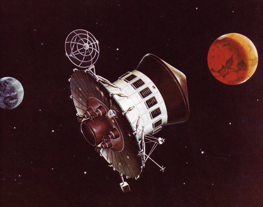
A ROMBUS vehicle during the final phase of its climb to orbit. Two liquid hydrogen tanks are shown immediately after separation; they are numbered incorrectly (they should be 5 and 6) and the tank at lower left has apparently experienced premature parachute deployment. The painting shows a small centerbody (with U.S. flag) and a disproportionately long cylindrical extension above it; both have reflective metal skin. Image credit: Douglas Aircraft Company via San Diego Air & Space Museum.

A NASA Landing Ship Dock retrieves the second of a pair of ROMBUS liquid hydrogen tanks. Also visible are the dome-shaped top of the first tank of the pair, the inside of the ship's well, one open well door, and two cranes. Image credit: Douglas Aircraft Company via San Diego Air & Space Museum.

Bono proposed that NASA acquire a surplus U.S. Navy Landing Ship Dock (LSD) for recovery of the floating tanks. LSDs were designed primarily to deploy landing ships bearing soldiers. Most of the space within an LSD's hull was taken up by a rectangular well that could be flooded. A pair of doors at the aft end of the ship opened the flooded well to the sea. Two cranes amidships, each capable of hoisting up to 50 U.S. tons/45.35 metric tons, could then be used to pull floating objects  such as ROMBUS liquid hydrogen tanks  into the well. 

After the well doors were closed, the water would be pumped out of the well so that objects taken in could be secured for transport using the cranes. Bono estimated that an LSD could retrieve and return to the LOC one pair of ROMBUS tanks at a time.

As ROMBUS ascent continued, two more opposing liquid hydrogen tanks would supply all fuel to the plug-nozzle engine, expend their contents, detach, tumble, and parachute to a splashdown 357 miles/575 kilometers downrange. The final opposing pair would separate at a low orbital altitude of 57.5 miles/92.5 kilometers and would, 19 minutes after separation from the ROMBUS centerbody, parachute into the Atlantic about 2760 miles/4440 kilometers downrange from the LOC. Bono estimated that tanks 5 through 8 would need additional thermal protection to withstand aerodynamic heating generated during their descent though Earth's atmosphere.

Bono provided no details of ROMBUS payload deployment or other orbital operations. Instead, he skipped to a novel reentry technique he believed the plug-nozzle engine would make possible. The technique would form a major element of the ROMBUS patent NASA was granted on his behalf in January 1967.

In its 200-mile-high/325-kilometer-high orbit, the centerbody would complete 16 orbits every 24 hours. The last of these orbits each day would carry it over an elliptical ROMBUS landing area centered between Orange City, Florida, and the Atlantic coast, about 30 miles/50 kilometers northwest of the ROMBUS launch complexes

Every 24 hours a radio command could thus be sent that would initiate centerbody return to the LOC. Upon receiving the command, the centerbody would face its plug-nozzle engine forward and briefly fire four combustion chamber segments spaced evenly around the combustion chamber slot. This maneuver would slow the centerbody by 500 feet per second/152 meters per second. With its plug-nozzle engine still facing forward, it would then begin its descent to the landing area.

Cutaway of the ROMBUS launch vehicle centerbody. Features are identified in the black and white illustration immediately below. Image credit: Douglas Aircraft Company via San Diego Air & Space Museum. 
The ROMBUS vehicle centerbody with important features labeled. Features are shown more clearly in the color image immediately above. Image credit: Douglas Aircraft Company via San Diego Air & Space Museum. 

Bono proposed that the forward-facing ROMBUS plug-nozzle engine could serve double-duty as a reusable active heat shield for protecting the centerbody from reentry heating. He believed that the system that cooled the plug-nozzle engine during ascent  liquid hydrogen flowing through tubes within the plug  could also keep the engine cool during reentry. Liquid hydrogen for the deorbit burn and reentry cooling would be carried in a spherical tank within the plug-nozzle engine. He suggested that, after cooling the plug, the hydrogen could be expelled through the plug-nozzle engine combustion chambers and turbopump nozzle, protecting them from reentry heating and further cooling the outside of the plug. 

In his 1963 paper Bono provided few details of his novel reentry method. In a 1976 book Bono co-authored with spaceflight writer Kenneth Gatland, however, he explained that plug-nozzle engine cooling would activate in "low-flow" mode as the centerbody descended below 400,000 feet/122,000 meters about 11 minutes before planned landing. After three minutes, as reentry heating neared its peak, cooling would switch to "high-flow" mode for four minutes. Then, four minutes before landing, the supply of cooling hydrogen would run out. 

A drogue parachute would deploy from the top of the centerbody to decelerate it below supersonic speed and enhance its stability. At an altitude of 30,000 feet/9145 meters, the drogue would detach and four or five main recovery parachutes would deploy. 

As the centerbody fell below 2500 feet/760 meters, the parachutes would detach and four combustion chambers would ignite. These would further slow descent and and steer the centerbody toward a precise landing spot. Bono suggested that a human on the ground aided by ground-based radar might remotely pilot the centerbody in the final descent phase. 

The centerbody would extend four landing legs. At touchdown, leg compression would trigger engine shutdown. At engine stop, the centerbody would weigh 500,000 pounds (227,000 kilograms) and stand 95 feet/29 meters tall. 

The ROMBUS launch vehicle centerbody ignites four of its combustion chamber segments and discards its main recovery chutes. Parts of each of the two zones (inner and outer) of the elliptical ROMBUS landing area are visible below the centerbody. The barge port is in view on the coast to the left of the centerbody, along with the road connecting it to the inner landing area zone; in the background, to the right of centerbody, Cape Canaveral and some of its spaceflight facilities can be seen. Image credit: Douglas Aircraft Company via San Diego Air & Space Museum. 
The centerbody has landed and a mobile platform crawler approaches. After the crawler picks up the centerbody, the four landing legs on the latter will be retracted. Image credit: Douglas Aircraft Company via San Diego Air & Space Museum. 

The ROMBUS mission would not be ended, however, for post-flight refurbishment constituted a critical and complex phase of operations. A U-shaped mobile platform on treads would be used to collect the centerbody and carry it overland from the landing site to a port facility on the Florida coast. There it would roll onto a barge to begin a 20-mile/30-kilometer journey south along the Intercoastal Waterway to the LOC. 

At the LOC, the barge would enter a canal leading to a special ROMBUS assembly building located north of the Saturn V Vertical Assembly Building (VAB). At the time Bono presented his paper, the VAB did not yet exist; construction began on 3 August 1963, less than two months after the AIAA Los Angeles meeting. Upon arrival at the ROMBUS assembly building, the mobile platform would disembark from the barge and deliver the centerbody to a refurbishment bay.

Partial cutaway of the ROMBUS vehicle assembly building at the Launch Operations Center, Cape Canaveral, Florida. The assembly building includes three bays. In the one at left, a payload shroud is lowered onto a ROMBUS vehicle; at right, a ROMBUS vehicle has left the building on its way to one of the four ROMBUS launch complexes, the nearest of which is at least 2.15 miles/3.45 kilometers away. At upper right, a barge arrives at the canal carrying a centerbody; at upper left, a Landing Ship Dock delivers a pair of ROMBUS liquid hydrogen tanks. Image credit: Douglas Aircraft Company via San Diego Air & Space Museum. 

Bono estimated normal ROMBUS turnaround time  which he defined as the time separating two launches  at 76 days. During that period, the centerbody would be partially disassembled, refurbished, reassembled, fitted with eight liquid hydrogen fuel tanks, loaded with a payload, and fitted with a launch shroud. A mobile platform crawler would then carry the launch vehicle to a ROMBUS launch complex for final preparations and a new flight to orbit.

Bono devoted two pages of his 20-page Los Angeles paper to text and charts detailing ROMBUS costs. He sought to prove that ROMBUS could yield a "four-fold improvement over current vehicles in (a) payload capability and (b) direct operating costs." ("Current launch vehicles" referred mainly to the Saturn family rockets.) On the whole, however, his cost estimates are not convincing, in large part because he failed to define his cost estimation methodology. 

He wrote of an annual ROMBUS program cost of $1 billion a year, and a total program cost including facilities, operations, and development of between $9 billion and $17 billion. Of this total, development cost ranged from $5.1 billion to $8.6 billion. 

Cost per pound of payload to orbit varied considerably depending on which factors Bono chose to consider. For example, he estimated that a reliability of 0.85 would yield a cost of $12 per pound/$26 per kilogram; upping reliability to 0.95, as might be achieved as NASA gained experience over the course of the ROMBUS program, would reduce cost to $5 per pound/$11 per kilogram.

In his 1976 co-authored book, Bono arrived at a cost of $25 per pound/$55 per kilogram if the ROMBUS vehicle could be reused 20 times; 100 reuses would reduce cost to $10 per pound/$22 per kilogram "or less." These estimates may reflect methodologies NASA applied in the early 1970s to generate Space Shuttle cost estimates, which would turn out to be seriously flawed.

Bono suggested that ROMBUS might be flown economically with less than its maximum payload. It would then amount to a "reusable 'trucking' system" that could replace existing smaller expendable launch vehicles. Flights with reduced payloads would need less liquid hydrogen fuel and liquid oxygen oxidizer; this meant that they would need fewer liquid hydrogen tank pairs. He wrote that, for a mission that would see ROMBUS launch a nuclear-thermal rocket upper stage to an altitude of 106,000 feet (32,300 meters) for a suborbital reactor start, the liquid oxygen tank in the centerbody would need only be filled halfway. 

NASA MSFC pulled the plug on the Douglas post-Saturn launch vehicle study in March 1964. This did not, however, prevent Bono from continuing to propose vehicles that resembled ROMBUS. In his 1976 co-authored book, for example, he described Hyperion, a sled-launched 55-passenger orbital crew transport; Pegasus, a suborbital 172-passenger crew/cargo transport capable of traveling 7456 miles/12,000 kilometers in just 39 minutes; and the Ithacus intercontinental troop transport, which could carry 260 soldiers and their equipment anywhere in the world. All were, like ROMBUS, reusable single-stage vehicles with plug-nozzle engines.

In June 1964, NASA MSFC director Wernher von Braun acknowledged publicly that post-Saturn launch vehicles had no future by calling publicly for future crewed planetary missions to use the Saturn V launch vehicle. By November of that year, President Lyndon Baines Johnson made clear that the NASA space program after Apollo should emphasize Earth-orbital operations and rely on rockets and spacecraft developed for the Apollo lunar landing program.

Sources

"ROMBUS - An Integrated Systems Concept for a Reusable Orbital Module (Booster & Utility Shuttle)," Douglas Engineering Paper No. 1552/AIAA Preprint No. 63-271, P. Bono, Douglas Aircraft Company; paper presented at the First National Summer Meeting of the American Institute of Aeronautics and Astronautics, Los Angeles, California, 18 June 1963.

Design No. 201,773. Recoverable Single Stage Spacecraft Booster, "James E. Webb, Administrator of the National Aeronautics and Space Administration, with respect to an invention of Philip Bono," US Patent Office, 16 June 1964 (filed), 27 July 1965 (granted),

Patent No. 3,295,790. Recoverable Single Stage Spacecraft Booster, "James E. Webb, Administrator of the National Aeronautics and Space Administration, with respect to an invention of Philip Bono," US Patent Office, 16 June 1964 (filed), 3 January 1967 (granted).

Frontiers of Space (Revised Edition), P. Bono and K. Gatland, MacMillan Publishing Company, 1976, pp. 63, 66, 69-70, 163-168, 197-200, 218.

Stages to Saturn: A Technological History of the Apollo/Saturn Launch Vehicles, NASA SP-4206, R. Bilstein, NASA, 1980, pp. 37, 50-60.

San Diego Air & Space Museum Image Collection (https://sandiegoairandspace.org/collection/image-collection — accessed 6 May 2025). 

More Information

Dyna-Soar's Martian Cousin (1960)

Reusable One-stage Orbital Space Truck (ROOST) (1962)

EMPIRE Building: Ford Aeronutronic's 1962 Plan for Piloted Mars/Venus Flybys

X-15: Lessons for Reusable Winged Spaceflight (1966)

Apollo-Soyuz II (1974)

Image credit: NASA.
The Apollo-Soyuz Test Project (ASTP) had its origins in talks aimed at developing a common U.S./Soviet docking system for space rescue. The concept of a common docking system was first put forward in 1970; it was assumed at that time, however, that the docking system would be developed for future spacecraft, such as the U.S. Space Station/Space Shuttle, not the U.S. Apollo Command and Service Module (CSM) and Soviet Soyuz spacecraft in operation at the time.

A joint U.S./Soviet space mission served the political aims of both countries, however, so the concept of a near-term docking mission rapidly gained momentum. In May 1972, at the superpower summit meeting held in Moscow, President Richard Nixon and Premier Alexei Kosygin signed an agreement calling for an Apollo-Soyuz docking in July 1975.

NASA and its contractors studied ways of expanding upon ASTP even before it was formally approved; in April 1972, for example, McDonnell Douglas proposed a Skylab-Salyut international space laboratory (see "More Information," below). A year and a half later (September 1973), however, the aerospace trade magazine Aviation Week & Space Technology cited unnamed NASA officials when it reported that, while the Soviets had indicated interest in a 1977 second ASTP flight, the U.S. space agency was "currently unwilling" to divert funds from Space Shuttle development.

Nevertheless, early in 1974 the Flight Operations Directorate (FOD) at NASA Johnson Space Center (JSC) in Houston, Texas, examined whether a second ASTP mission might be feasible in 1977. The 1977 ASTP proposal aimed to fill the expected gap in U.S. piloted space missions between the 1975 ASTP mission and the first Space Shuttle flight.

Cutaway illustration of ASTP Apollo Command Module (lower left), ASTP Docking Module (DM), ASTP Soyuz Orbital Module, and ASTP Soyuz Descent Module (upper right). The three U.S. crewmembers wear brown coveralls. Image credit: NASA.
The brief in-house study focused on mission requirements for which NASA JSC had direct responsibility. FOD assumed that Apollo CSM-119 would serve as the prime 1977 ASTP spacecraft and that the U.S. would again provide the Docking Module (DM) for linking the Apollo CSM with the Soyuz spacecraft. CSM-119 had been configured as the five-seat Skylab rescue CSM; work to modify it to serve as the 1975 ASTP backup spacecraft began as FOD conducted its study, soon after the third and final Skylab crew returned to Earth in February 1974. FOD suggested that, if a backup CSM were deemed necessary for the 1977 ASTP mission, then the incomplete CSM-115 spacecraft should get the job. CSM-115, which resided in storage in California, had been tapped originally for the cancelled Apollo 19 moon landing mission.

FOD also assumed that the ASTP prime crew of Thomas Stafford, Vance Brand, and Deke Slayton would serve as the backup crew for the 1977 ASTP mission, while the 1975 ASTP backup crew of Alan Bean, Ronald Evans, and Jack Lousma would become the 1977 ASTP prime crew. FOD conceded, however, that this assumption was probably not realistic. If new crewmembers were needed, FOD noted, then training them would require 20 months. They would undergo 500 hours of intensive language instruction during their training.

FOD estimated that Rockwell International support for the 1977 ASTP flight would cost $49.6 million, while new experiments, nine new space suits, and "government-furnished equipment" would total $40 million. Completing and modifying CSM-115 for its backup role would cost $25 million. Institutional costs — for example, operating Mission Control and the Command Module Simulator (CMS), printing training manuals and flight documentation, and keeping the cafeteria open after hours — would add up to about $15 million. This would bring the total cost to $104.7 million without the backup CSM and $129.7 million with the backup CSM.

The FOD study identified "two additional major problems" facing the 1977 ASTP mission, both of which involved NASA JSC's Space Shuttle plans. The first was that the CMS had to be removed to make room for planned Space Shuttle simulators. Leaving it in place to support the 1977 ASTP mission would postpone Shuttle simulator availability.

A thornier problem was that 75% of NASA JSC's existing flight controllers (about 100 people) would be required for the 1977 ASTP in the six months leading up to and during the mission. In the same period, NASA planned to conduct "horizontal" Space Shuttle flight tests. These would see a Shuttle Orbiter flown atop a modified 747; later, the aircraft would release the Orbiter for an unpowered glide back to Earth. FOD estimated that NASA JSC would need to hire new flight controllers if it had to support both the 1977 ASTP and the horizontal flight tests. The new controllers would receive training to support Space Shuttle testing while veteran controllers supported the 1977 ASTP.

ASTP Apollo spacecraft and Saturn IB rocket sit atop the "milkstool" on Launch Pad 39B, Kennedy Space Center, Florida. Image Credit: NASA.
ASTP Soyuz 19 spacecraft and Soyuz rocket lift off from Baikonur Cosmodrome in Soviet central Asia. Image credit: NASA.
The ASTP Apollo CSM (CSM-111) lifted off on a Saturn IB rocket on 15 July 1975 with astronauts Thomas Stafford, Vance Brand, and Donald Slayton on board. The ASTP Saturn IB, the last rocket of the Saturn family to fly, lifted off from Launch Complex (LC) 39 Pad B, one of two Saturn V pads at Kennedy Space Center, not the LC 34 and LC 37 pads used for Saturn IB launches in the Apollo lunar program. This was because NASA had judged that maintaining the Saturn IB pads for Skylab and ASTP would be too costly. A "pedestal" (nicknamed the "milkstool") raised the Skylab 2, 3, and 4 and ASTP Saturn IB rockets so that they could use the Pad 39B Saturn V umbilicals and crew access arm.

Once in orbit, the ASTP CSM turned and docked with the DM mounted on top of the Saturn IB's second stage. It then withdrew the DM from the stage and set out in pursuit of the Soyuz 19 spacecraft, which had launched about eight hours before the Apollo CSM with cosmonauts Alexei Leonov and Valeri Kubasov on board. The two craft docked on 17 July and undocked for the final time on July 19. Soyuz 19 landed on 21 July. The ASTP Apollo CSM, the last Apollo spacecraft to fly, splashed down near Hawaii on 24 July 1975 — six years to the day after Apollo 11, the first piloted Moon landing mission, returned to Earth.

Conceptual illustration of proposed Space Shuttle/Salyut docking. Image credit: Junior Miranda.
U.S. Space Shuttle Atlantis docked with the Russian Mir space station, 4 July 1995, as imaged from the Russian Soyuz TM-21 spacecraft. Image credit: NASA.
The proposal for a 1977 ASTP repeat gained little traction. Though talks aimed at a U.S. Space Shuttle docking with a Soviet Salyut space station had resumed in May 1975, no plans for new U.S.-Soviet manned missions existed when the ASTP Apollo splashed down. Shuttle-Salyut negotiators made progress in 1975-1976, but the U.S. deferred signing an agreement until after the results of the November 1976 election were known.

In May 1977, the sides formally agreed that a Shuttle-Salyut mission should occur. In September 1978, however, NASA announced that talks had ended pending results of a comprehensive U.S. government review. Following the December 1979 Soviet invasion of Afghanistan, work toward joint U.S.-Soviet piloted space missions was abandoned on advice from the U.S. Department of State. It would resume a decade later as the Soviet Union underwent radical internal changes that led to its collapse in 1991 and the rebirth of the Soviet space program as the Russian space program.

Sources

"Second ASTP Unlikely," Aviation Week & Space Technology, 3 September 1973, p. 13.

Memorandum for the Record, "information. . . developed in estimating the cost of flying a second Apollo-Soyuz Test Project (ASTP) mission in 1977," NASA Johnson Space Center, 4 April 1974.

Thirty Years Together: A Chronology of U.S.-Soviet Space Cooperation, NASA CR 185707, David S. F. Portree, February 1993.

More Information

Skylab-Salyut Space Laboratory (1971)

"Still Under Active Consideration": Five Proposed Apollo Earth-Orbital Missions for the 1970s (1971)

NASA's 1992 Plan to Land Soyuz Space Station Lifeboats in Australia

SEI Swan Song: International Lunar Resources Exploration Concept (1993)

Testing Shuttle Manipulator Arms During Earth-Orbital Apollo Missions (1971-1972)

In this drawing by NASA engineer Caldwell Johnson, twin human-like Space Shuttle robot arms with human-like hands deploy from the Apollo Command and Service Module (CSM) Scientific Instrument Module (SIM) Bay to grip the derelict Skylab space station. Image credit: NASA/Caldwell Johnson.
Caldwell Johnson, co-holder with Maxime Faget of the Mercury space capsule patent, was chief of the Spacecraft Design Division at the NASA Manned Spacecraft Center (MSC) in Houston, Texas, when he proposed that astronauts test prototype Space Shuttle manipulator arms and end effectors during Apollo Command and Service Module (CSM) missions in Earth orbit. In a February 1971 memorandum to Faget, NASA MSC's director of Engineering and Development, Johnson described the manipulator test mission as a worthwhile alternative to the Earth survey, space rescue, and joint U.S./Soviet CSM missions then under study. 

At the time Johnson proposed the Shuttle manipulator arm test, three of the original 10 planned Apollo lunar landing missions had been cancelled, the second Skylab space station (Skylab B) appeared increasingly unlikely to reach orbit, and the Space Shuttle had not yet been formally approved. NASA managers foresaw that the Apollo and Skylab mission cancellations would leave them with surplus Apollo spacecraft and Saturn rockets after the last mission to Skylab A. They sought low-cost Earth-orbital missions that would put the surplus hardware to good use and fill the multi-year gap in U.S. piloted missions expected to occur in the mid-to-late 1970s.

Johnson envisioned Shuttle manipulators capable of bending and gripping much as do human arms and hands, thus enabling them to hold onto virtually anything. He suggested that a pair of prototype arms be mounted in a CSM Scientific Instrument Module (SIM) Bay, and that the CSM "pretend to be a Shuttle" during rendezvous operations with the derelict Skylab space station. 

The CSM's three-man crew could, he told Faget, use the manipulators to grip and move Skylab. They might also use them to demonstrate a space rescue, capture an "errant satellite," or remove film from SIM Bay cameras and pass it to the astronauts through a special airlock installed in place of the docking unit in the CSM's nose. 

Image credit: NASA/Caldwell Johnson.
Faget enthusiastically received Johnson's proposal (he penned "Yes! This is great" on his copy of the February 1971 memo). The proposal generated less enthusiasm elsewhere, however. 

Undaunted, Johnson proposed in May 1972 that Shuttle manipulator hardware replace Earth resources instruments that had been dropped for lack of funds from the planned U.S.-Soviet Apollo-Soyuz Test Project (ASTP) mission. President Richard Nixon had called on NASA to develop the Space Shuttle just four months before (January 1972). Johnson asked Faget for permission to perform "a brief technical and programmatic feasibility study" of the concept, and Faget gave him permission to prepare a presentation for Aaron Cohen, manager of the newly created Space Shuttle Program Office at MSC. 

In his June 1972 presentation to Cohen, Johnson declared that "[c]argo handling by manipulators is a key element of the Shuttle concept." He noted that CSM-111, the spacecraft tagged for the ASTP mission, would have no SIM Bay in its drum-shaped Service Module (SM), and suggested that a single 28-foot-long Shuttle manipulator arm could be mounted near the Service Propulsion System (SPS) main engine in place of the lunar Apollo S-band high-gain antenna, which would not be required during Earth-orbital missions. 

During ascent to orbit, the manipulator would ride folded beneath the CSM near the ASTP Docking Module (DM) within the streamlined Spacecraft Launch Adapter. During SPS burns, the astronauts would stabilize the manipulator so that acceleration would not damage it by commanding it to grip a handle installed on the SM near the base of the CSM's conical Command Module (CM). 

Johnson had by this time mostly dropped the concept of an all-purpose human hand-like "end effector" for the manipulator; he informed Cohen that the end effector design was "undetermined." The Shuttle manipulator demonstration would take place after CSM-111 had undocked from the Soviet Soyuz spacecraft and moved away to perform independent maneuvers and experiments. 

The astronauts in the CSM would first use a TV camera mounted on the arm's wrist to inspect the CSM and DM, then would use the end effector to manipulate "some device" on the DM. They would then command the end effector to grip a handle on the DM, undock the DM from the CSM, and use the manipulator to redock the DM to the CSM. Finally, they would undock the DM and repeatedly capture it with the manipulator.

Caldwell Johnson's depiction of a prototype Shuttle manipulator arm with a hand-like end effector. The manipulator grasps the Docking Module meant to link U.S. Apollo and Soviet Soyuz spacecraft in Earth orbit during the Apollo-Soyuz Test Project (ASTP) mission. Image credit: NASA/Caldwell Johnson. 
Johnson estimated that new hardware for the ASTP Shuttle manipulator demonstration would add 168 pounds (76.2 kilograms) to the CM and 553 pounds (250.8 kilograms) to the SM. He expected that concept studies and pre-design would be completed in January 1973. Detail design would commence in October 1972 and be completed by 1 July 1973, at which time CSM-111 would undergo modification for the manipulator demonstration.

Johnson envisioned that MSC would build two manipulators in house. The first, for testing and training, would be completed in January 1974. The flight unit would be completed in May 1974, tested and checked out by August 1974, and launched into orbit attached to CSM-111 in July 1975. Johnson optimistically placed the cost of the manipulator arm demonstration at just $25 million. 

CSM-111, the last Apollo spacecraft to fly, reached Earth orbit on schedule on 15 July 1975. By then, Caldwell Johnson had retired from NASA. CSM-111 carried no manipulator arm; the tests Johnson had proposed had been judged to be unnecessary. 

That same month, the U.S. space agency, short on funds, invited Canada to develop and build the Shuttle manipulator arm. The Remote Manipulator System — also called the Canadarm — first reached orbit on board the Space Shuttle Columbia during STS-2, the second flight of the Shuttle program, on 12 November 1981. 

During Space Shuttle mission STS-7 (18-24 June 1983), the crew of the Orbiter Challenger used the Canada-built Remote Manipulator System (RMS) arm to deploy and retrieve a small satellite. In this image, the deployed RMS is bent to form a numeral "7." Image credit: NASA. 

Sources 

Memorandum with attachment, EW/Chief, Spacecraft Design Division, to EA/Director of Engineering and Development, "Flight Demonstration of Shuttle docking and cargo handling techniques and equipment using CSM/Saturn 1-B," NASA Manned Spacecraft Center, 1 February 1971. 

Memorandum with attachment, EW/Chief, Spacecraft Design Division, to PA/Special Assistant to the Manager, "Demonstration of Shuttle manipulators aboard CSM/Soyuz rendezvous and docking mission," NASA Manned Spacecraft Center, 25 May 1972. 

Memorandum with attachment, EW/Chief, Spacecraft Design Division, to LA/Manager, Space Shuttle Program Office, "Proposal to Demonstrate Shuttle-type Manipulator During Apollo/Soyuz Test Project," NASA Manned Spacecraft Center, 28 June 1972. 

More Information


Viking on the Moons of Mars (1972)

Phobos, the inner moon of Mars, as imaged by the Viking 1 Orbiter. Viking images of Deimos, Mars's outer moon, can be found at the bottom of this post. Image credit: NASA.
In June 1972, NASA Langley Research Center (LaRC) in Hampton, Virginia, contracted with Martin Marietta Corporation to look at using spacecraft based on the planned Viking Mars Lander and Orbiter designs to explore the martian moons Phobos and Deimos. NASA LaRC managed Project Viking, which aimed to launch two Lander/Orbiter combinations toward Mars in 1975, while Martin Marietta was prime contractor for the Viking Lander. The Jet Propulsion Laboratory (JPL) in Pasadena, California, built the Mariner-derived Viking Orbiter.

Viking was the stepchild of the Voyager Program, first proposed by JPL in 1960. Voyager, which had as its major goal the discovery and detailed study of life on Mars, had suffered from management ineptitude, turf battles, schedule slips, and a comprehensive redesign (and attendant cost increase) resulting from new Mars data gathered during the Mariner IV Mars flyby (July 1965).

The Voyager spacecraft as envisioned at the time of its cancellation in 1967. The lander is packaged in the dark-colored aeroshell at upper right. Image credit: NASA.
In an unusual move, top NASA officials met with leaders of Congress shortly after Voyager's cancellation in August 1967 to seek funding for a replacement. The latter agreed to fund Viking starting in Fiscal Year 1969, which began on 1 October 1968. Like Voyager, Viking would seek life on Mars. Congressional leaders also agreed to fund a pair of Mariner Mars orbiters that would launch in 1971.

Mariner Mars 1971, Viking, and the proposed Viking-based Phobos/Deimos missions were all in part a response to declared Soviet space plans. As NASA astronauts explored Earth's Moon, the Soviet Union proclaimed to the world that they had never meant to accomplish the same feat; that they had in fact opted to explore space using robots because they would not place human lives at risk. They pointed to their robotic Luna lunar sample-returners and Lunokhod 1 lunar rover when they claimed that they would soon dispatch robot orbiters, landers, sample-returners, and rovers throughout the Solar System. 

The Mariner VII spacecraft glimpsed Phobos during its fast Mars flyby in 1969, and the Mariner 9 orbiter returned the first clear images of both martian moons in November 1971, while Martin Marietta's study was underway. Mariner 8, Mariner 9's twin and planned fellow traveler, had fallen into the Atlantic Ocean north of Puerto Rico after the failure of its Centaur upper stage on 9 May 1971. 

Phobos and Deimos were the first non-spherical Solar System bodies humankind examined close up. They revolve about Mars in circular equatorial orbits. Phobos completes one orbit in about 7.5 hours at an altitude of about 5980 kilometers (3715 miles), while Deimos orbits in about 30 hours at 20,070 kilometers (12,470 miles). 

Phobos measures 21 by 25 kilometers (13 by 16 miles) and Deimos is about half as large. Small size means low gravity; Phobos has only about 0.1% as much surface gravity as Earth. Because of this, setting down on Phobos or Deimos would be more like docking than landing.

Viking Orbiter (top) shortly after release of the aeroshell containing the Viking Lander. Image credit: NASA/Don Davis.
A Viking Lander samples the surface of Mars in this artist's concept from March 1974. Image credit: U.S. Geological Survey/Don Davis.
NASA LaRC directed Martin Marietta to assume that its Viking-based Phobos/Deimos missions would depart Earth in the 1979 and 1981 Earth-Mars minimum-energy transfer opportunities. The study report described several Phobos/Deimos spacecraft designs. 

The first, the baseline Phobos/Deimos landing spacecraft, would comprise a heavily modified Viking Lander and a Viking Orbiter with tanks carrying 38% more propellants than the Viking 1975 design (Martin Marietta called this a "38% Stretch Orbiter"). Mass at Earth-orbit departure would total about 3600 kilograms (7940 pounds) during the 1979 minimum-energy Earth-Mars transfer opportunity. The Lander would account for 482 kilograms (1063 pounds) of that mass. 

Upon arrival at Mars, the Orbiter would fire its rocket motor to slow down and place itself and the attached Mars moon Lander into an elliptical, equatorial "capture orbit" about the planet. The spacecraft would then maneuver into an elliptical, 15-hour "observation orbit." The apoapsis (high point) of this orbit would reach the orbit of Deimos, while its periapsis (low point) would dip inside the orbit of Phobos. 

The spacecraft would repeatedly fly past both moons, gathering data at each encounter so that scientists on Earth could decide which moon most warranted in-depth exploration. Controllers would then command the spacecraft to match orbits with the moon selected. 

The Lander would separate from the Orbiter and move toward its target using Viking Lander attitude-control thrusters. It would set down gently on three spidery legs and deploy 82 kilograms (181 pounds) of instruments, including a seismometer, a surface sample auger, and a boom-mounted camera. The Lander would be able to hop across the surface in the weak gravity by briefly firing its thrusters; an alternate mobility scheme would employ spindly umbrella-shaped wheels at the ends of the landing legs. 

Viking Lander-derived Phobos/Deimos rover. Image credit: Martin Marietta/NASA.
Martin Marietta proposed an alternate baseline mission in which the Viking Orbiter would land on the target moon. This more efficient "landed orbiter" scenario could land about 500 kilograms (1100 pounds) of science instruments, the company estimated. Total cost for a baseline Phobos/Deimos landing mission would come to $324 million.

The company targeted its second design, the baseline Phobos/Deimos sample-return spacecraft, for launch in 1981 "to allow more time for additional mission design and hardware development." The sample-return mission would build on experience gained in the 1979 landing mission. Its 3374-kilogram (7438-pound) spacecraft would consist of a 38% Stretch Viking Orbiter with four legs and a 260-kilogram (573-pound) drum-shaped Earth-return vehicle based on a proposed Venus Pioneer spacecraft design. 

The Orbiter would land on the target moon, collect a two-kilogram (4.4-pound) sample, and transfer it to a sample-return capsule inside the Earth-return vehicle. The Earth-return vehicle would then fire its rocket to separate from the landed Orbiter and maneuver into a 1500-by-95,000-kilometer (930-by-59,000-mile) Mars orbit. There it would trim its orbital plane so that the subsequent Mars departure maneuver could place it on course for Earth. 

Near Earth, the saucer-shaped sample-return capsule would separate from the Earth-return vehicle. It would enter Earth's atmosphere at up to 12.8 kilometers (8 miles) per second, slow to subsonic speed, deploy a parachute, and lower to a soft landing. The baseline sample-return mission would cost a total of $446 million. 

Martin Marietta's third design, the baseline combined Phobos/Deimos landing and Mars landing spacecraft, would comprise a minimally modified Viking Lander and a 26% Stretch Viking Orbiter. Total weight at Earth-orbit departure would come to 4150 kilograms (9150 pounds) in 1979. 

For this "Mars + Phobos/Deimos landing" mission, the Orbiter would fire its rocket to place itself and the Viking Lander into an elliptical equatorial capture orbit about Mars requiring 97 hours to complete, then would release the lander. De-orbiting from the capture orbit would impose restrictions on the Lander — it would be able to set down only within a latitude band extending 12° north and 12° south of Mars's equator and would need a beefed-up heat shield to withstand a greater Mars atmosphere entry velocity. 

The Orbiter would then maneuver to a 15-hour observation orbit, match orbits with either Phobos or Deimos, and land bearing 62 kilograms (137 pounds) of science instruments. The baseline combined mission would cost $441 million. 

Martin Marietta also considered "Mars + Phobos/Deimos observation orbit," "Mars + Phobos/Deimos rendezvous," and "Mars + Phobos/Deimos sample-return" missions. Its "Mars +" missions would, the company estimated, be more cost-effective than Phobos/Deimos missions without Mars landings. A separate Phobos/Deimos landing mission would, for example, cost 80% as much as a Mars landing mission, while a "Mars + Phobos/Deimos landing" mission would cost only 14% more than a Mars landing mission. 

Martin Marietta then looked at whether sufficient interest existed in the planetary science community to justify missions to the martian moons. The company found that there were "no active and forceful champions" of Phobos/Deimos exploration. It added, however, that it had 
repeatedly found easily excited curiosity and conjecturing among space scientists about the origin and nature of these tiny bodies. This undercurrent of scientific interest, which has been given impetus by the recent returns of Mariner 9, may be the forerunner of well defined and enthusiastically supported recommendations for exploring the moons of Mars. If this is the case, NASA's decision to conduct this study may prove to be a very timely one. 
Viking 1 left Earth atop a Titan III-E rocket with a Centaur upper stage on 20 August 1975. Viking 2 launched on 9 September 1975. The twin two-part spacecraft entered Mars orbit on 19 June 1976, and 7 August 1976, respectively. The Viking 1 Lander separated from its Orbiter and touched down successfully on 20 July 1976; Viking 2's Lander followed on 3 September 1976. 

While the Landers operated on the surface, the Orbiters imaged Mars and its satellites. On 15 October 1977, the Viking 2 Orbiter passed just 30 kilometers (19 miles) from Deimos (images at bottom of post). 

NASA supported studies of a Viking-derived Moon lander, a Viking 1979 Mars rover mission, and other Viking derivatives, but the U.S. opted not to fund new missions based on Viking technology. Much like the $25-billion Apollo Program, Project Viking — which had cost over $1 billion in 1975 dollars (about $5 billion in 2023 dollars) — ended with its potential barely exploited. 

This occurred because the Soviet Union did not keep its promise to explore the Solar System, because NASA's budget shrank to half its Apollo-era value, and because public interest slumped after the Viking search for life on Mars returned equivocal results. The U.S. would launch no new spacecraft toward Mars until 1992, two decades after Martin Marietta completed its study. 

Deimos as imaged by the Viking 2 Orbiter. Image credit: NASA.
Individual house-sized boulders and craters submerged in dust are visible in this Viking 2 Orbiter close-up of Deimos. Image credit: NASA.

Sources

A Study of System Requirements for Phobos/Deimos Mission, Final Report, Volume I, Summary, Martin Marietta Corporation, June 1972.

On Mars: Exploration of the Red Planet, 1958-1978, NASA SP-4212, Edward Clinton Ezell and Linda Neumann Ezell, NASA, 1984, pp. 83-153.

More Information


Space Shuttle External Tank (ET) Applications: ET as Space Facility (1982)

Big tank: External Tank-1, with the Space Shuttle Orbiter Columbia and twin Solid Rocket Boosters attached, arrives at Launch Pad 39-A at NASA Kennedy Space Center, Florida, after its roll-out from the Vehicle Assembly Building on 29 December 1980. Note the fire truck for scale. Image credit: NASA.
NASA announced in August 1973 that it had awarded Martin Marietta Corporation a $107-million contract to develop the Space Shuttle External Tank (ET). The initial contract called for the manufacture of three ground test ETs and six flight test ETs. The first Shuttle flight test was expected as early as 1977.

Four years later (9 September 1977), the first ET rolled off the Martin Marietta assembly line at NASA Michoud Assembly Facility, near New Orleans, Louisiana. By the next day, the space agency had moved the tank the short distance to the National Space Technology Laboratories (NSTL — now called NASA Stennis Space Center) in southern Mississippi. 

The 153.8-foot-long (46.9-meter-long), 27.5-foot-diameter (8.4-meter-diameter) ET included three major parts, all made mostly of aluminum alloy. Its forward third, shaped like a fat teardrop for streamlining, was the 19,500-cubic-foot (552-cubic-meter), 55-foot-long (16.8-meter-long) liquid oxygen (LOX) tank. Its aft two-thirds was the 53,500-cubic-foot (1515-cubic-meter), 97-foot-long (29.6-meter-long) liquid hydrogen (LH2) tank, a cylinder with dome-shaped ends. The two pressure vessels partially nested in the drum-shaped intertank, which measured 22 feet (6.7 meters) in length. The nine ETs delivered under the initial Martin Marietta contract each weighed about 38.6 U.S. tons (35 metric tons) empty. 

First tank: the Main Propulsion Test Article (MPTA) External Tank (ET) rolls off the Martin Marietta assembly line at Michoud Assembly Facility, Louisiana, on 9 September 1977. The three major ET components are discernible; the ribbed intertank separates the cylindrical liquid hydrogen (LH2) tank, the largest component, from the streamlined liquid oxygen tank at left. Please note the LH2 tank aft dome just clearing the door at right. Image credit: NASA.
Though unveiled amid much ceremony, the first ET was not intended for flight. Instead, it became the largest component of the Main Propulsion Test Article (MPTA). Other MPTA parts included a sturdy truss that stood in for the Shuttle Orbiter and a cluster of three Space Shuttle Main Engines (SSMEs) attached to the truss. The MPTA was hoisted vertical, mounted on an NSTL test stand, and put to work in SSME tests. 

On 29 June 1979, Martin Marietta rolled out the first flight ET. NASA loaded ET-1 onto a barge and shipped it across the Gulf of Mexico, around the southern tip of Florida, and up the Atlantic coast to NASA Kennedy Space Center (KSC). There the tank was moved to the Vehicle Assembly Building (VAB) and mated to a pair of Solid Rocket Boosters (SRBs) and the Orbiter Columbia in preparation for the first mission of the Space Transportation System (STS), which was aptly designated STS-1.

NASA rolled the STS-1 stack out of the VAB on 29 December 1980. Four months later (12 April 1981), it lifted off from Launch Complex 39-A. On board Columbia for her maiden flight were astronauts John Young and Robert Crippen. Shortly after the first Orbiter's triumphant return to Earth, NASA reduced the number of flight tests to four, freeing two of the flight test ETs for operational flights. 

The ET performed two critical functions during every Shuttle flight. It carried about 800 U.S. tons (725 metric tonnes) of LH2 fuel and LOX oxidizer for the three SSMEs in the Orbiter's tail; in addition, it bound together and provided thrust load paths for the 120-U.S.-ton (109-metric-tonne) Orbiter and twin 650-U.S.-ton (590-metric-tonne) SRBs. Together the three SSMEs on the Orbiter and the SRBs generated about seven million pounds (31,100,000 newtons) of thrust at liftoff.

The SRBs expended their propellants and separated from attachment fixtures on either side of the ET about two minutes after liftoff. They fell into the ocean and were recovered for reuse. The ET supplied propellants to the SSMEs for a further six and a half minutes; then, shortly after SSME shutdown, it was cast off and made to tumble to hasten its fall into Earth's atmosphere. When the ET separated from the Orbiter, it typically contained about 15 tons of leftover propellants (weight is approximate, so U.S. and metric units both apply). Reentry destroyed the ET; surviving pieces fell in remote ocean areas.

Orbiter and ET attained about 98% of orbital velocity before the latter was discarded. Two small Orbital Maneuvering System (OMS) engines in the Orbiter's tail then supplied the remaining 2% of the velocity needed to boost it, its crew, and its payload into a stable circular orbit about the Earth.

The process by which NASA arrived at the Shuttle design was complex. Until mid-1971, most designs paired a reusable, winged, piloted Orbiter with a reusable, winged, piloted Booster. The latter would have released the former just short of orbit. In most designs, the Booster would then have performed a wide 180° turn, deployed jet engines, and flown to a runway landing near its launch site. The semi-reusable Orbiter/ET/SRB stack, forced on NASA by funding limits imposed by President Richard Nixon, was, by comparison, a kludge — but in the minds of some spaceflight planners, it created an opportunity.

Beginning about the time the MPTA ET rolled out at Michoud, planners proposed that NASA boost ETs into orbit and put them to use. Some assumed that the ET would supply the SSMEs with LOX and LH2 until orbit was attained. Others assumed that the SSMEs would shut down just short of orbital velocity as during a normal flight, but that the Orbiter would retain the ET; then, when the twin OMS engines ignited to complete injection into orbit, it would bring the ET along for the ride.

When one reads of plans to exploit the ET in space, it is important to recall the giddy optimism many felt during Shuttle development in the 1970s. It started early — for example, the aerospace industry publication Aviation Week & Space Technology reported at the time Martin Marietta won its initial ET contract that NASA anticipated that 439 flight ETs would be manufactured through 1984. Assuming a first launch at the start of 1977, this implied a Shuttle launch every six days. 

The Shuttle, it was expected, would fly so cheaply that NASA would be able to spend the lion's share of its human spaceflight budget on payloads the Orbiter could carry to orbit in its 15-by-60-foot (4.6-by-18.3-meter) payload bay, not on transportation costs. At a bare minimum, such payloads would include government and commercial satellites and components and supplies for an expansive Space Station that Orbiter crews would assemble in orbit.

Proposed ET uses fell into three categories: propellant scavenging, exploitation of ET aluminum, and conversion of ET structures. LOX and LH2 scavenged from the ET could, some estimated, economically supply Space Tugs based at the Space Station; they would transport astronauts and cargo throughout cislunar space. Ground up or melted down, ETs could become propellant for aluminum-burning rocket engines, aluminum girders and trusses for large space structures, and reaction mass for electromagnetic mass drivers. Partially disassembled or clustered, ETs might be converted into space habitats, telescopes, propellant depots, warehouses, greenhouses, space warfare decoys, and platforms for instruments and weapons.

Brown tank: liftoff of Columbia at the start of STS-4, the final Orbital Flight Test mission (27 June-4 July 1982). Only STS-1 and STS-2 flew with white tanks; starting with STS-3, NASA opted not to paint the ETs. Image credit: NASA.
In July 1982, shortly after STS-4, the last Shuttle flight test, Martin Marietta completed a study for NASA Marshall Space Flight Center of the Aft Cargo Carrier (ACC) (see "More Information" below). Structurally similar to the ET — the company envisioned that it would be manufactured at Michoud using ET tooling and jigs — the ACC would ride to orbit attached to the dome-shaped aft end of the ET LH2 tank. As might be expected given Martin Marietta's ET expertise, the ACC proposal was among the most technically credible of the many ET exploitation schemes put forward in the late 1970s and 1980s.

As its name implies, the ACC, which would include two sections, was intended chiefly to augment Shuttle payload capacity. Use of the 27.5-foot-diameter (8.4-meter-diameter), 31.9-foot-long (9.7-meter-long) ACC with the Shuttle Orbiter payload bay would nearly double maximum Shuttle payload diameter and volume. Other ACC applications were possible, however; its lower section might, for example, serve as a protective shroud covering a "Space Facility Module" bolted to the ET LH2 tank aft dome. The ACC shroud would shield the drum-shaped pressurized module from the harsh thermal and acoustic environment the SRBs would create at the aft end of the ET during Shuttle ascent.

This image of the two-part Martin Marietta Aft Cargo Carrier (ACC) shows its proximity in flight to the three Space Shuttle Main Engines mounted to the Orbiter's tail. The Solid Rocket Boosters can be assumed to have detached; typically they would obstruct the view of the ACC from this angle. The ACC is mounted to and covers the aft dome of the ET liquid hydrogen tank. Image credit: Martin Marietta.
Space Facility Modules would have different functions, but all would include a vertical cylindrical airlock that would enable astronauts to take advantage of a circular 36-inch (91.4-centimeter) "manhole" in the LH2 aft dome. A feature of all ETs, the manhole was designed to permit technicians on the ground to access the LH2 tank interior during ET checkout and launch preparation. In space, it would enable astronauts to enter and convert the LH2 tank for a range of purposes.

Space Facility Modules would thus resemble the Spent Stage Experiment Support Module (SSESM) proposed in the early 1960s for use with Apollo Saturn S-IVB rocket stages. The S-IVB, the second stage of the two-stage Saturn IB rocket and the third stage of the three-stage Saturn V, included in its upper two-thirds an LH2 tank. The drum-shaped SSESM, launched attached to the top of a Saturn IB S-IVB, would have enabled astronauts to enter the empty LH2 tank to outfit it in orbit as an Earth-orbiting space station. A 1966 plan proposed landing a Saturn V-launched SSESM/S-IVB combination on the Moon (see "More Information" below). 

Space Facility Module: the Service Module. Please note the off-center, slanted port at top, just left of center; conforming to the shape of the aft dome of the ET liquid hydrogen tank, it would enable access to the manhole located there. The Service Module has five additional ports; two radial ports with petal-type docking units and the tunnel leading to the aft port are visible. Image credit: Martin Marietta.
The company described the rapid growth of an Earth-orbiting Space Facility space station. The first Space Facility launch would see an Orbiter boost an ET with attached Space Facility Module — configured as a "Service Module" — into a 215-nautical-mile-high (398.2-kilometer-high) orbit. During ascent, 15 seconds after the SRBs separated from the Shuttle stack, the lower section of the ACC shroud would separate and fall away, exposing the Service Module. The Orbiter would retain the ET, firing its SSMEs until the desired orbit was achieved.

The Orbiter crew would vent residual ET propellants through the SSMEs and would hand off ET stabilization to an attitude control/orbit-maintenance propulsion system in the Service Module, then would separate their spacecraft from the ET/Service Module combination and perform station-keeping with it. The Service Module would deploy a pair of electricity-producing solar arrays and orient them toward the Sun. 

The Space Facility would include three Docking/Service Tunnels. Image credit: Martin Marietta.
The astronauts would next open the Orbiter payload bay doors and use the Remote Manipulator System (RMS) robot arm to hoist a "Docking/Service Tunnel" out of the payload bay. After linking the tunnel to an aft-facing port on the Service Module, they would dock the Orbiter with the tunnel. They would then enter the newly established Space Facility.

In addition to its propulsion system, power system, and airlock linking it to the ET LH2 tank, the Service Module would contain life support systems and living and working space for several astronauts. Its single pressurized volume would, however, only be occupied if an Orbiter were docked to it; this was a safety measure meant to ensure that the crew could reach a safe haven in the event of Space Facility depressurization, fire, or atmospheric contamination.

Space Facility Module: the Habitat Module. Image credit: Martin Marietta.
Addition of a second ET with Space Facility Module — this time configured as a "Habitat Module" — would remove that restriction. The Orbiter and ET/Habitat Module would rendezvous with the Space Facility; then, after separation, the crew would hoist a second Docking/Service Tunnel out of the payload bay and link it to one of four radial (side-mounted) ports on the Service Module. The ET/Habitat Module would then move or be moved (by a means not described) so that it could link one of its radial ports with the second tunnel, binding the two Space Facility Module/ET combinations together.

The astronauts would next use the RMS to hoist a Logistics Module out of the payload bay. They would attach the small module, which would contain supplies and small experiment apparatus, to one of the four Habitat Module radial ports. With that task completed, they would dock with and enter the Space Facility. With the addition of the Habitat Module, astronauts could remain on board after the Orbiter departed.

The third Space Facility assembly flight would see a Shuttle Orbiter arrive with a full payload bay and no ET or Space Facility Module. A third Docking/Service Tunnel would be hoisted from the payload bay and linked to a Service Module radial port, then a small piloted space tug designed for satellite deployment, retrieval, and repair would be docked to the new tunnel. 

Finally, an experiment pallet based on the Spacelab pallet designed originally for operation in the Orbiter payload bay would be attached to the exterior of one of the ETs. It would be the first of many experiment payloads that would employ the ETs as stable space platforms. 

The Space Facility would be fully operational after just three Shuttle flights. Attached to the ETs at center right are the Service Module with twin solar arrays and the Habitat Module. An experiment pallet designed originally to conform to the Shuttle payload bay stands out against the ET exterior just left of image center. In this artist's conception other components — a logistics module with black stripes, a small space tug, and the Docking/Service Tunnel to which the Orbiter is docked — are incorrectly depicted. See post text for their correct locations and sizes. Image credit: Martin Marietta/DSFPortree.
By the time the Orbiter departed for the third time, the Space Facility would, Martin Marietta declared, enable "a permanent manned presence in space." The services it offered, the company added, would "significantly complement. . .the basic Shuttle capability." 

Martin Marietta saw no reason to stop there. It proposed that astronauts would eventually outfit the interiors of the Space Facility's ET LH2 tanks with decks and furnishings. NASA might also expand the Space Facility by adding new ETs. These could be converted in orbit into hangars for storing and servicing satellites. The 27.5-foot-diameter (8.4-meter-diameter) LH2 tank would, the company noted, provide ample room for satellites sized for launch in the Orbiter payload bay.

Space Facility expansion: a scheme for outfitting the interior of an ET liquid hydrogen tank as a comfortable habitat housing 16 astronauts. Image credit: Martin Marietta.
Martin Marietta's Space Facility concept died an early death in large part because it was seen to compete with NASA's Space Station plans, which favored trusses and modules sized for launch in the Shuttle payload bay. After January 1984, when President Ronald Reagan called on the space agency to build a Space Station, plans to exploit ETs as habitats, hangars, or platforms stood almost no chance of acceptance.

Sources

"News Digest," Aviation Week & Space Technology, 20 August 1973, p. 25. 

"Shuttle Tanks Undergo Tests at Michoud," Aviation Week & Space Technology, 23 May 1977, p. 49. 

"The Low (Profile) Road to Space Manufacturing," G. O'Neill, Astronautics & Aeronautics, Vol. 16, No. 3, March 1978, pp. 24-32. 

"NASA Studying Shuttle-Derived Launch Vehicles," Aviation Week & Space Technology, 8 March 1982, p. 81.

"NASA Seeks Shuttle Capability Growth," C. Covault, Aviation Week & Space Technology, 23 April 1982, pp. 42-43, 45, 47, 51-52.

"Martin Studies Shuttle Aft Cargo Unit," E. Kolcum, Aviation Week & Space Technology, 12 July 1982, p. 65-66. 

"External Tank Applications in Space," K. Timmons, A. Norton, and F. Williams, Martin Marietta; paper presented at the Unispace Conference in Vienna, Austria, 9-17 August 1982.

"External Tank Depicted as Space Station Element," Aviation Week & Space Technology, 6 September 1982, p. 246.

External Tank ACC Aft Cargo Carrier, Martin Marietta, no date (late 1982).

More Information

S-IVB/IU Applications: The LASS Proposal (1966)

Where to Launch and Land the Space Shuttle? (1971-1972)

One Space Shuttle, Two Cargo Volumes: Martin Marietta's Aft Cargo Carrier (1982)