 |
| Douglas Aircraft Company built the S-IVB stage and IBM built the Instrument Unit (IU) that rode atop it. In the image above, the S-IVB/IU combination for the Apollo 4 mission is hoisted in the Vertical Assembly Building at NASA Kennedy Space Center (KSC), Florida. The black ring at the top is the IU; the red object mostly hidden by the tapered interstage adapter at the bottom is the S-IVB's J-2 rocket engine bell in a red protective wrapping. The study described in this post drew to its conclusion as this, the first S-IVB/IU intended for flight, began pre-launch preparations at KSC. Apollo 4, the first flight test of the Saturn V, flew without a crew on 9 November 1967. The Apollo 4 S-IVB/IU performed flawlessly. Image credit: NASA. |
Finding new roles for space hardware that exists or is under development is a common objective of spaceflight advance planners. They aim to accomplish new tasks in space while reducing development time and cost; if they work for a contractor and propose new roles for hardware that their company is on contract to produce, they might also hope to generate new contracts and new revenue. Advance planners employed by NASA may also seek to find new ways to exploit existing hardware; their objectives in doing so can often be complex.
Many examples of proposals to repurpose space hardware can be cited. The reader may explore some of them by clicking on links in the "More Information" section at the bottom of this post.
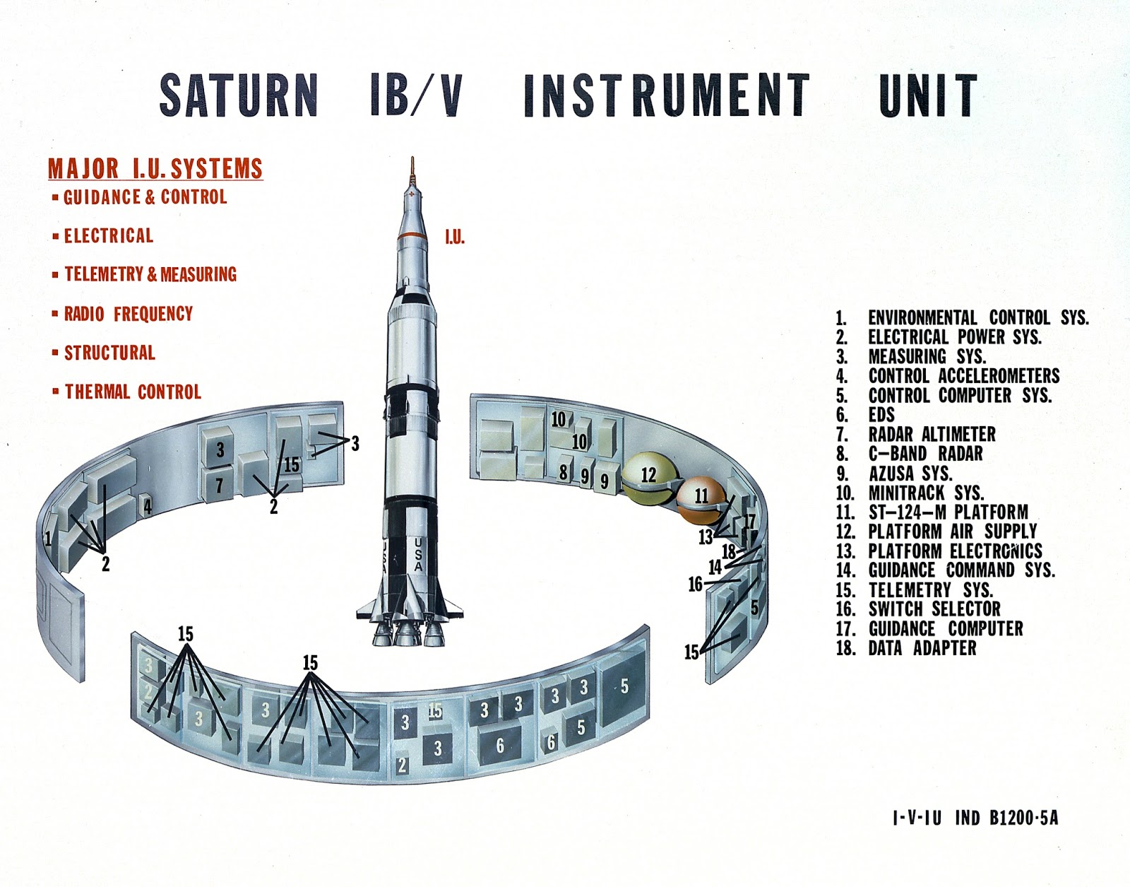
In this post we zero in on a proposal for repurposing two important elements of Apollo-era space hardware: the S-IVB rocket stage, which formed the second stage of the two-stage Saturn IB launch vehicle and the third stage of the three-stage Saturn V launcher, and the Instrument Unit (IU), the "electronic brain" of the Saturn IB and Saturn V, which rode into space bolted atop the S-IVB. The authors of this proposal were engineers at Douglas Aircraft Company, the prime contractor of the S-IVB, and International Business Machines (IBM), the prime contractor of the IU.
 |
| Image credit: NASA. |
 |
| Image credit: NASA. |
The Douglas/IBM team performed its "Lunar Applications of a Spent S-IVB/IU Stage (LASS)" study using company funds between November 1965 and July 1966, shortly after the official start within NASA of the Apollo Applications Program (AAP) in August 1965. During AAP, the U.S. civilian space agency encouraged and invited proposals for new uses of hardware under development for the Apollo lunar program.
The S-IVB and IU were designed to reach Earth orbit during Apollo Earth-orbital missions and to leave Earth orbit with enough energy to fly past the Moon during Apollo lunar missions. This meant that, even without modifications, they would reach places in space where they might serve new useful purposes. As AAP gained steam in the 1965-1966 period, the S-IVB and IU thus became prime candidates for application to new missions throughout cislunar space and beyond.
The LASS proposal grew out of a 1964 plan to make use of the Saturn IB S-IVB stage in low-Earth orbit. The S-IVB, which included (from top to bottom) a large tank for liquid hydrogen (LH2) fuel, a smaller tank for liquid oxygen (LOX) oxidizer, and a single J-2 engine capable of generating about 200,000 pounds (890,000 newtons) of thrust, would typically reach Earth orbit with an Apollo Command and Service Module (CSM) spacecraft on top during Apollo Earth-orbital missions. The CSM would weigh about 40,000 pounds (18,145 kilograms).
The large enclosed volume of its tanks and the payload it could place into orbit made the S-IVB a natural candidate for exploitation as the basis for an Earth-orbital laboratory. In 1965-1966, the favored scheme was to launch a two-stage Saturn IB with a modified S-IVB second stage carrying a Spent-Stage Experiment Support Module (SSESM) in place of a CSM with a crew. At the time the Douglas/IBM team performed the LASS study, the first S-IVB/SSESM combination was scheduled to reach Earth orbit early in 1968 as part of the SA-209 AAP mission.
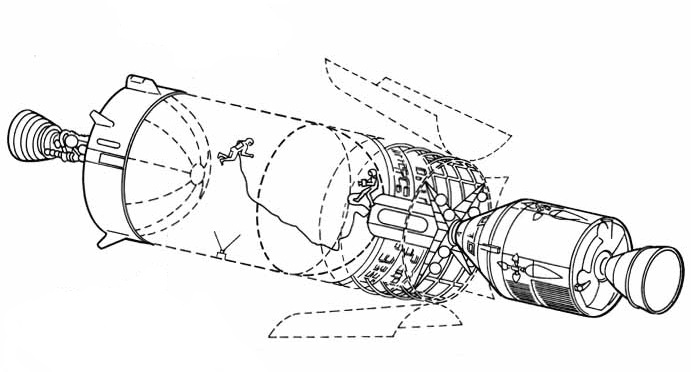
 |
| An S-IVB-derived Earth-orbital laboratory with an attached Spent-Stage Experiment Support Module (SSESM) and, at right, a docked, separately launched Apollo Command and Service Module (CSM). Image credit: NASA. |
After reaching orbit, commands transmitted from the ground — or perhaps generated automatically by its attached IU — would cause the S-IVB to vent leftover propellants from its tanks. A second Saturn IB rocket would then launch a CSM with a crew of three.
The astronauts would dock their CSM with the SSESM, which might contain equipment, life support consumables, and furnishings they could use to make the S-IVB LH2 tank into a habitable living and working space with 10,400-cubic-feet (295.5 cubic meters) of volume. Other plans for using of the S-IVB in Earth orbit saw the SSESM as the only pressurized volume; the LH2 tank would in that case provide an enclosed space for experiments performed in vacuum. The SSESM would include an airlock which space-suited astronauts could use to enter the LH2 tank.
The Douglas/IBM team called their proposed LASS program a "sequel" to the use of spent S-IVB stages in Earth orbit. The team anticipated that, after a development program spanning 45 months, the first automated LASS vehicle might deliver a 27,300-pound (12,380-kilogram) payload to the lunar surface and provide a "sheltered volume" on the Moon as early as the 1970-1971 period.
A LASS mission would begin with a Saturn V liftoff from a Launch Complex 39 pad at Kennedy Space Center, Florida. The rocket would comprise an unmodified S-IC first stage, an unmodified S-II second stage, and a modified S-IVB third stage — the LASS vehicle — with a payload on top under an aerodynamic nose cone. The Douglas/IBM team suggested that the 3200-pound (1450-kilogram) nose cone planned for Voyager automated Mars/Venus spacecraft launches might be repurposed for LASS launches.
Until the S-II stage shut down, LASS Saturn V ascent would closely resemble Apollo Saturn V ascent. In both cases, the S-II would separate from the spent S-IC stage two minutes and 41 seconds after liftoff at an altitude of 42 miles (68 kilometers) and ignite its five J-2 engines. The S-IVB or LASS vehicle would then separate from the S-II stage eight minutes and 40 seconds after liftoff at an altitude of about 109 miles (175 kilometers).
During Apollo missions, four forward-facing small retro-rocket motors on the tapered adapter linking the bottom of the 21.7-foot-diameter (6.6-meter-diameter) S-IVB with the top of the 33-foot-diameter (10-meter-diameter) S-II would fire immediately after S-II shutdown. This would slow the S-II slightly to facilitate S-IVB separation. The adapter, though considered part of the S-IVB, would remain attached to the S-II when the S-IVB separated.
Small rocket engines on twin side-mounted Auxiliary Propulsion System (APS) pods would then fire to accelerate the S-IVB slightly. This would cause the weightless LH2 and LOX propellants within it to settle to the bottom of their tanks so that they could enter intakes leading to the S-IVB J-2 engine. The J-2 would then ignite to boost the S-IVB and its payload to low-Earth parking orbit.
 |
| LASS vehicle launch configuration. Image credit: Douglas Aircraft Company/IBM. |
 |
| Procedure for LASS vehicle landing leg deployment and separation from the Saturn V S-II stage. Image credit: Douglas Aircraft Company/IBM. |
 |
| LASS vehicle engine and plumbing arrangement. Image credit: Douglas Aircraft Company/IBM. |
LASS vehicle separation from the adapter linking it to the S-II stage would be more complicated. Four landing legs folded against the outside of the adapter under covers protecting them from aerodynamic heating during ascent would deploy, then a dozen forward-facing "ordinance thrusters" spaced 30° apart around top of the adapter would ignite to slow the S-II slightly to facilitate LASS vehicle separation.
Replacing the four small retro-rockets on the Apollo Saturn V S-IVB/S-II adapter with 12 thrusters was necessary because the LASS vehicle included two RL-10 engines mounted on either side of its J-2 engine. Even with the RL-10 engine bells fully gimballed (pivoted) toward the J-2, LASS vehicle separation from the adapter using only the four retro-rockets would have been a risky business. Four thrusters would have meant less precision even if all worked as planned; in addition, the Douglas/IBM team estimated that if just one retro-rocket motor failed, collision between an RL-10 and the adapter was guaranteed.
The versatile RL-10 engine had been developed for the Centaur, the world's first LH2/LOX rocket stage. Combining throttleable RL-10 engines with Saturn hardware was nothing new when the Douglas/IBM team performed the LASS study; the Saturn I rocket, the first flightworthy member of the Saturn family, had mounted at the bottom of its S-IV second stage six RL-10s, each capable of producing 15,000 pounds (66,720 newtons) of thrust.
 |
| First Saturn I launch: SA-1, 27 October 1961. Image credit: NASA. |
 |
| Image credit: NASA. |
 |
| Image credit: NASA. |
Saturn I had been intended to launch astronauts into low-Earth orbit, but it was relegated to Apollo development flights without crews after NASA decided in 1962 that Saturn IB and Saturn V should become the Apollo launch vehicles. The last Saturn I flight, SA-10, launched a non-functional mass simulator ("boilerplate") Apollo CSM and the Pegasus III micrometeoroid detection satellite on 30 July 1965, a little more than three months before the LASS study commenced.
Use of the RL-10 as a LASS rocket engine was deemed necessary because the standard J-2 engine could not be throttled or gimballed enough to permit the LASS vehicle to land on the Moon. The Douglas/IBM team noted, however, that, if the proposed advanced J-2X engine were developed outside the LASS program — that is, without cost to the LASS development effort — then a single J-2X might replace the baseline J-2 engine and twin RL-10s.
After successful LASS vehicle separation from the adapter and S-II, motors in its twin APS modules would fire to accelerate it slightly, causing the weightless propellants within it to settle to the bottom of their tanks. There they would enter intakes leading to the RL-10 and J-2 engines.
The three engines would ignite to perform a single 8.5-minute Trans-Lunar Injection (TLI) burn that would expend 171,800 pounds (77,930 kilograms) of propellants to place the LASS vehicle on course for a 110-hour (4.5-day) voyage to the Moon. LASS vehicle mass would total 131,800 pounds (59,535 kilograms) at the end of the TLI burn. The LASS vehicle would then discard the aerodynamic nosecone covering its top-mounted payload.
The LASS TLI scheme was a significant departure from its Apollo counterpart. During Apollo lunar missions, the S-IVB J-2 would first burn for about 2.5 minutes, injecting it and the attached Apollo spacecraft into a 118-mile-high (190-kilometer-high) parking orbit about the Earth; then, about 2.5 hours after launch, it would burn again for about six minutes to depart parking orbit for the Moon.
Loitering in parking orbit would permit a final checkout of Apollo spacecraft systems. Even more important, however, it would make available a daily launch window spanning several hours on each day of a monthly lunar launch window spanning several days. This flexibility would allow NASA to compensate for delays that might occur during the complex Saturn V pre-launch countdown.
The LASS vehicle's direct-ascent lunar mission profile would, by contrast, permit only a very brief launch window (in theory, it would be instantaneous). Direct-ascent, while worrisome from the standpoint of launching to any given lunar landing site during any given launch opportunity, would reduce the quantity of propellants expended to launch the LASS vehicle to the Moon. This would make available more propellants for two planned course corrections and for the all-important lunar landing burn.
Following the TLI burn, thrusters in the APS modules, governed by navigational electronics in the IU, would maneuver the LASS vehicle so that its three engines and the bottom of its LOX tank pointed at the Sun. This orientation would help to prevent the LASS vehicle's LH2 fuel from causing its LOX oxidizer to freeze. The RL-10 engines, meanwhile, would cyclically vent excess gaseous hydrogen that built up in the LH2 tank.
 |
| Technicians assemble an Instrument Unit (IU) at the IBM plant in Huntsville, Alabama. In their study, the Douglas/IBM team assumed that the interior walls and portions of the central area of the IU might be used to house new LASS vehicle systems. Image credit: NASA. |
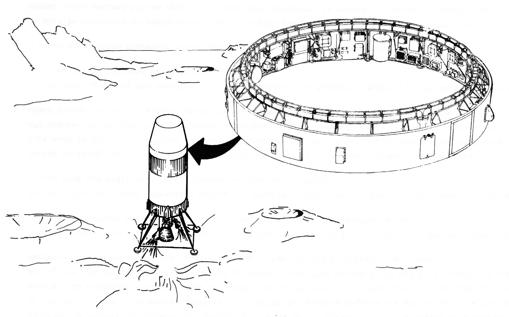
 |
| The LASS vehicle just before touchdown on the lunar surface. The illustration displays the position of the IU and, above it, the tapered LASS vehicle payload volume. Image credit: Douglas Aircraft Company/IBM. |
The Douglas/IBM team considered the IU to be a candidate location for many new LASS vehicle systems. New navigation and communications systems, for example, would include long-range and short-range lunar landing radars, an altimeter, sensors for tracking the Sun, Earth, stars, and the lunar horizon, a data transmission system including a steerable high-gain dish antenna mounted on the outside of the IU, and a system for homing in on a pre-landed radio beacon at the target landing site on the Moon.
Though the IU would include new navigational systems, it would still rely heavily on navigational data transmitted from Earth. The Douglas/IBM team expected that reliance on Earth-provided data — which would be generated using inputs from both Earth-based tracking and IU sensors — would ensure that the LASS vehicle could navigate successfully using 1966 state-of-the-art technology. Avoidance of new navigational systems would help to control LASS vehicle development cost.
The IU would also offer a candidate location for electricity-generating systems. These would include three Apollo CSM-type fuel cells, their thermal radiator, and tanks containing their LH2/LOX reactants, as well as rechargeable silver-zinc batteries for handling peak electrical demands during course corrections and the lunar landing burn. The fuel cells would provide three kilowatts of power continuously for the duration of the 110-hour LASS vehicle flight; the batteries would support peak loads of up to 6.76 kilowatts.
Between 10 and 20 hours after launch, the LASS vehicle would perform its first course correction maneuver. The IU would orient the LASS vehicle for the burn using the APS thrusters, then would pressurize the LH2 tank and J-2 engine using helium drawn from spherical "bottles" mounted on the inner walls of the LH2 tank and on the thrust structure supporting the J-2 and RL-10 engines.
The RL-10s, which could be ignited without propellant settling, would burn in "10% idle mode" to settle propellants so that they could reach the J-2 engine, then would throttle up as the J-2 ignited. After the three engines fired for a predetermined period of time, they would shut down and the IU would orient the LASS vehicle so that they would again point toward the Sun. If data supplied from Earth indicated that it was necessary, a second course correction would take place between 60 and 100 hours into the flight.
Unlike the Apollo CSM and LM spacecraft, the LASS vehicle would not inject into lunar orbit before descent to its target landing site. Instead, about 15,000 miles (24,140 kilometers) from the Moon and roughly 107 hours after liftoff, the Terminal Landing Phase (TLP) would commence. The IU would reorient the LASS vehicle so that its engines and four landing leg footpads pointed toward the Moon. At TLP start, LASS vehicle mass would total 117,500 pounds (53,300 kilograms).
About two hours later, at an altitude of about 450 miles above the Moon, the lunar horizon sensor would confirm LASS vehicle orientation. At an altitude of 350 miles, the IU would lock onto the signal from the pre-landed beacon at the landing site. The IU computer would begin performing TLP tracking calculations once per second.
The RL-10 and J-2 engines would ignite to begin TLP Phase I braking at an altitude of 350,000 feet (160,680 meters). At 40,000 feet (12,190 meters), the altimeter would begin to supply data to the IU computer, supplementing beacon tracking data.
TLP Phase II braking would begin with J-2 shutdown at 25,000 feet (7620 meters). At 10,000 feet (3050 meters), the IU would cease homing on the beacon. The IU computer would then very sensibly seek, as the Douglas/IBM team put it, to "drive all velocities relative to the surface to zero."
 |
| LASS vehicle landing legs and footpads. Image credit: Douglas Aircraft Company/IBM. |
The IU would throttle the RL-10 engines to maintain a vertical descent velocity of 10 feet (three meters) per second and a lateral velocity of less than three feet (one meter) per second. When the IU-mounted short-range landing radar indicated an altitude of 70 feet (21.3 meters) above the Moon, the LASS vehicle's footpads would be about 10 feet (three meters) from the surface. The IU would then shut down the RL-10s and the LASS vehicle would drop the remaining distance.
The Douglas/IBM team judged that their TLP system could enable a touchdown within 500 feet (150 meters) of the pre-landed beacon. LASS vehicle mass at touchdown would total 63,580 pounds (28,840 kilograms). Of this, payload above the IU would total up to 27,300 pounds (12,380 kilograms).
Immediately after touchdown, the IU would command the LASS vehicle to "passivate" itself. The Douglas/IBM team did not describe the passivation process in any detail, though its aim would be to evacuate vessels containing liquids and gases that might freeze, leak, or over-pressurize and burst their containers. For example, about 2000 pounds (910 kilograms) of leftover LH2 and LOX propellants in the LASS vehicle tanks would be vented overboard. Gases and liquids in the payload would, of course, be immune from passivation.
After an unspecified period of time, astronauts would land near the LASS vehicle in an Apollo LM. The Douglas/IBM team provided few details about how the crew would interact with the LASS vehicle. They offered only a few vague suggestions concerning, for example, how astronauts in bulky space suits might ascend the approximately 60 feet (18.3 meters) to the top of the LASS vehicle to reach the payload. Neither did they describe how payload items would be moved from the top of the LASS vehicle to the surface, though they suggested that unspecified "cargo & handling equipment" with a mass of 3100 pounds (1400 kilograms) would be available. These and other mysteries would no doubt have been addressed if NASA had opted to fund additional LASS studies.
The Douglas/IBM engineers did, however, define five typical LASS payload configurations and mission durations. All would feature lunar exploration hardware under consideration in 1966 for AAP lunar missions and would see IU navigational and communications electronics serve double-duty as experiment data support equipment.
Configuration 1 was most in keeping with the role of the LASS vehicle as a sequel to an S-IVB-derived laboratory in low-Earth orbit. The LASS vehicle's LH2 tank would be lined with 3940 pounds (1785 kilograms) of micrometeoroid shielding and thermal insulation before launch from Earth; this weight would be subtracted from the weight available for payload above the IU.
About 7700 pounds (3490 kilograms) of the payload above the IU would take the form of a two-man shelter similar to the SSESM proposed for the Earth-orbiting S-IVB laboratory. Life support gases and liquids and other expendables would account for 4500 pounds (2040 kilograms) of the payload. Experiment apparatus with a total weight of 500 pounds (227 kilograms), a 1000-pound (454-kilogram) unpressurized Lunar Scientific Survey Module (LSSM) rover, and a one-or-two-person Lunar Flying Unit (LFU) of unspecified weight would make up the balance of the payload.
 |
| LASS vehicle candidate lunar surface payload: Lunar Scientific Survey Module (LSSM) rover. Image credit: NASA. |
 |
| LASS vehicle candidate lunar surface payload: Lunar Flying Unit. Image credit; Bell Aerospace. |
Configuration 1 would see the two astronauts lower themselves into the LASS vehicle LH2 tank by unspecified means through an airlock in the shelter. The LH2 tank would then serve as either a laboratory or an emergency shelter. The crew would live in the LASS vehicle for up to 14 days before they reactivated their LM and returned to the Apollo CSM waiting in lunar orbit.
The other four LASS payload configurations would not make use of the LH2 tank, so the weight of the shielding and insulation surrounding it in Configuration 1 could be applied to payload above the IU. Configuration 2, with a 30-day lunar surface stay time, would include a 13,000-pound (5900-kilogram) four-man shelter, a 3800-pound (1725-kilogram) small (though possibly pressurized) rover, 4500 pounds (2040 kilograms) of science equipment, and 5700 pounds (2585 kilograms) of expendables. The Douglas/IBM team did not explain how four astronauts could reach the LASS vehicle on the Moon using the three-man CSM and two-man LM.
Configuration 3 would include a four-man shelter, an LSSM, science equipment, and 8500 pounds (3855 kilograms) of expendables. The four-person crew would remain on the Moon for 59 days. Configuration 4 would include a two-person shelter, a small rover, scientific equipment, and 11,000 pounds (4990 kilograms) of expendables. The crew would evenly divide their time during their 120-day lunar surface stay between the shelter and the small rover. Configuration 5 would include a two-person shelter, an LSSM, scientific equipment, and 13,800 pounds (6260 kilograms) of expendables. The crew would evenly divide their time during their 195-day stay between the shelter and the LSSM.
The Douglas/IBM team suggested that the astronauts might tip the roughly 60,000-pound (27,215-kilogram) LASS vehicle on its side to place its payload above the IU — which in this case would not include a shelter — close to the lunar surface. They did not, however, explain how the astronauts might accomplish this feat. They suggested that the crew could live inside their LM while they unloaded equipment from the tipped LASS vehicle and converted its LH2 tank into a shelter.
A LASS vehicle with more extensive modifications — for example, a large rectangular hole cut into its LH2 tank for mounting a telescope — might be tipped on its side and converted into a lunar surface astronomical observatory. Ultimately, multiple upright and tipped LASS vehicles might be dragged together to form a "LASS Modular Lunar Base." The Douglas/IBM engineers ended their report by declaring that "LASS is envisioned to be the vehicle to support all lunar surface programs."
During the 1960s, Douglas, IBM, and other contractors studied other new roles for the S-IVB and IU. These included a lunar-orbital lab, a testbed for reusable single-stage-to-orbit vehicles, a communications relay supporting missions to the Moon's farside hemisphere, a delivery vehicle for multiple automated lunar landers based on the Apollo LM descent stage, a testbed for interplanetary heat shield tests, and an interplanetary booster for automated and piloted spacecraft. Some of these are described in the "More Information" section below. Others will be described in future posts.
Sources
"NASA Launch Vehicles," Aviation Week & Space Technology, 2 July 1962, p. 91.
"Rendezvous to Slash Apollo Target Time," Aviation Week & Space Technology, 2 July 1962, pp. 106-111.
"Marshall Supervises Booster Development," Aviation Week & Space Technology, 2 July 1962, pp. 113-125.
Lunar Orbit Rendezvous — News Conference on Apollo Plans at NASA Headquarters on July 11, 1962, News Release and Press Conference Transcript, NASA, 1962.
Lunar Applications of a Spent S-IVB/IU Stage (LASS), presentation by Douglas Aircraft Company Missile & Space Systems Division and International Business Machines Federal Systems Division, September 1966.
"NASA Adapting S-4B for Space Station," W. Normyle, Aviation Week & Space Technology, 5 September 1966, p. 34.
"Manned Lunar Program Options Mission Modes," TM-67-1012-5, C. Bendersky & D. R. Valley, Bellcomm, Inc., 5 May 1967, pp. 9-10.
"Lunar Applications of a Spent S-IVB/IU Stage (LASS)," Douglas Paper No. 4256, L. O. Schulte & D. E. Davin, Douglas Missile & Space Systems Division; paper presented at the American Institute of Aeronautics and Astronautics Fourth Annual Meeting and Technical Display in Anaheim, California, 23-27 October 1967.
Stages to Saturn: A Technological History of the Apollo/Saturn, NASA SP-4206, Roger Bilstein, 1980, pp. 58-85, 129-153, 157-190, 241-257, 323-329, 336-345, 414-415.
More Information
One-Man Space Station (1960)
Space Station Gemini (1962)
Space Station Resupply: A 1963 Plan to Turn the Apollo Spacecraft Into a Space Freighter
Re-Purposing Mercury: Recoverable Space Observatory (1964)
"Still Under Active Consideration": Five Proposed Earth-Orbital Apollo Missions for the 1970s (1971)
Evolution vs. Revolution: The 1970s Battle for NASA's Future
Talking to the Farside: A 1963 Proposal to Use the Apollo Saturn V S-IVB Stage as a Radio Relay
Relighting the FIRE: A 1966 Proposal for Piloted Interplanetary Mission Reentry Tests
NASA's Planetary Joint Action Group Piloted Mars Flyby Study (1966)
"Without Hiatus": The Apollo Applications Program in June 1966
The First Voyager (1967)


I knew the J-2 had a restart capability, but I didn't realize it was considered throttleable (or could be made throttleable). I didn't realize there was a J-2X concept in the 1960s. When I think of J-2X, I think of the engine developed for the Ares I rocket. I guess that engine was never completed, either. But the RL-10 is alive and well.
ReplyDeletePerhaps two Saturn V launches could send four astronauts to the lunar surface. Wonder how much enthusiasm there really was for tipping over an S-IVB stage with people around.
The Starship lunar lander also will be a big, tall vehicle.
I had to educate myself about early rocket engine evolution for this one! I discovered that some work toward a J-2 as capable as the Douglas/IBM team wanted was carried out as part of a J-2S development program, but that it wasn't clear at the time they performed their study whether that would lead anywhere. They didn't want to take on the J-2X development cost (they didn't provide an estimate of how much that might cost), so they went; for the dual RL-10 approach. As for the rest of it — putting four astronauts on the Moon and keeping two astronauts on the Moon for more than six months — all that would clearly require some new development! I suppose they might have put two astronauts on the surface and then let the CSM pilot go home, then sent a pickup CSM and automated LM near the end of their surface stay, but the risks seem way outside the Apollo-era comfort zone. dsfp
DeleteIt's interesting how studies like this reflect the state of technology and plans at the time they are developed, but likely not what would have been on a final vehicle--at the very least, a flown LASS in 1972 or so probably would be using second-block Saturn Vs and thus probably J-2S, with improved thrust and specific impulse, throttling, and even a lo-thrust "idle mode". Probably still might have needed RL-10s, but performance ight have actually gone _up_ from this initial study.
DeleteI think that's likely. I didn't get into it, but the study looked at the effects of some upgrades — for example, using slush hydrogen — on payload delivered to the Moon. So they were thinking about ways of going beyond the planned S-IVB design even in 1965-1966. It was also in their interest, however, to "prove" that their system could be built without any upgrades — that the hardware could be exactly as planned at the time of the study and still deliver new capabilities. I got the sense they were trying to balance the AAP creed (new applications for Apollo hardware without much change) with a desire to move beyond Apollo limitations. dsfp
DeleteThe idea of using a J-2 for lunar landing is interesting, because few lunar landers use the same type of engines for TLI and landing.
ReplyDeleteThat's a really good point. Back in the science fiction days of the 1960s, atomic rockets modeled on the V-2 lifted off from Earth, flew to the Moon, and landed, all using the same engines and without staging. That turned out to be impractical in real life, of course. This comes close to that, however! dsfp
DeleteA LESA revisit would be a good follow up.
ReplyDeleteI'll keep that in mind. There's so many fascinating studies I need to cover — I doubt I'll ever cover even half of them. That being said, I'll certainly try. dsfp
DeleteIt’s interesting that LASS, unlike the Apollo CSM-LM stack, used the same engines for landing and TLP, engines that were not individually developed for the purpose.
ReplyDeleteThe Terminal Lunar Phase (TLP) maneuver is special to descent ascent missions, as best I can tell. In a mission that does a Lunar Orbit Insertion (or stops at EML1, or whatever), that doesn't happen until after the spacecraft pauses somewhere so that the crew can transfer to a lander. One thought that occurred to me while I wrote this — and I'm not sure that it's too important — is that a direct ascent profile like that used by LASS (and, BTW, Surveyor) would be riskier than one that inserts into lunar orbit. The crew would be falling toward the Moon, so if they had problems — if their engines didn't light up, say — they'd be in deep trouble. They'd also not be on a path to loop around the Moon and return to Earth the way early Apollo flights were. LASS and Surveyor didn't carry crews, so if they suffered problems they'd crash, but no one would die. dsfp
DeleteUntil I saw the picture "An S-IVB-derived Earth-orbital laboratory[etc.]" I'd never realised quite how much volume there is inside the S-IVB stage, it's enormous! I can see now why there were so many plans to empty the propellants out and use them as a space station/moon base.
ReplyDeleteRegarding the plans for the four man shelter, perhaps they planned to land two LMs, possibly stripped back ones that could (in a pinch) carry all four astronauts back into orbit. That way there would be some redundancy in case of problems with one of the landers.
The S-IVB stage is described in a public affairs literature as "cavernous," which is a bit of an exaggeration, truth be told (though volumes that can be pressurized as large as the S-IVB LH2 tank are rare in space). We're used to really compact pressurized volumes. One thing that always struck me about Skylab — a large part of the LH2 tank was mostly empty. I suspect that if we'd evolved Skylab we'd have flown a version with more (3-4) decks. I can't address how four astronauts would have reached the LASS vehicle on the Moon — it just isn't covered in the LASS report! What you suggest, however, might have been workable. One thing about LASS that troubled me a little — using the big LH2 tank volume only occurred with the smallest crew staying for the shortest time. Outfitting the LH2 ate into the mass available for life support consumables for a long stay. I think they would have had to address that tradeoff eventually. dsfp
DeleteI guess the S-IVB SSTO testbed you mentioned was Bono's SASSTO. Loved your last post on ROOST, I hope you have the studies for SASSTO and other Bono projects lying around for future posts. Thanks for all your work on this amazing site!
ReplyDeleteYes, SASSTO (I think that's right — one of my sources seemed to indicate there was a "pre-SASSTO" S-IVB scheme designed for plug nozzle testing, though I could have misunderstood that). I will indeed be writing about other Bono studies. I've got his ROMBUS study on my desk now. I figure LASS and ROOST are kind of similar (both Douglas, both focused on launch vehicles), so I'm going to do some other topics before I come back to ROMBUS and Bono's other work. Variety is the spice of life! dsfp
DeleteThat statement, projected use of only existing assets. (I paraphrase.) Explains a lot. My concept of using the MLV-3 to launch a CSM LM & Lunar 'Truck' with MOLAB all on the same vehicle would have to have started as a two Saturn-V launch and later combine it with the MLV-3.
ReplyDeleteYou always stimulate thought.
Kerry: It's good to know that! Thanks for sharing your ideas — they stimulate thought, too. dsfp
DeleteIt is aways amusing to see plans like this that amounted to "well we got this big ol' pressurized volume in space, there ought to be SOMETHING we can do with it". It's not difficult to launch low-density structures into orbit; the difficult part was figuring out how to *land* them, and how to keep humans alive (and doing useful things) in them, and these proposals invariably handwaved that away, apparently assuming that the astronauts would just pack an engine hoist and a cutting torch and "make do"...
ReplyDeleteIt's like I explain in the post — once a company (or other entity) sells a piece of space hardware, it's natural for that company (or other entity) to attempt to sell it again in repurposed form. At the time this study was performed, the Johnson Administration had made it clear that it would not support a post-Apollo space program based on new hardware — only Saturn/Apollo hardware would be acceptable. Douglas had the added incentive in this instance of encouragement from NASA re: using the S-IVB stage in LEO. If this company-funded trial balloon had excited some interest, perhaps NASA would have funded a study that fleshed out the concept, perhaps in connection with NASA-funded work on the S-IVB-derived Earth orbital spent-stage lab. dsfp
Delete