Showing posts with label Apollo Applications Program. Show all posts

The Proper Course for Lunar Exploration (1965)

Image credit: NASA.

For a time in the early 1960s, Thomas Evans headed up the Advanced Lunar Missions Study Program in the NASA Headquarters Office of Manned Space Flight. By May 1965, when the 11th Annual Meeting of the American Astronautical Society (AAS) was held in Chicago, Illinois, he had retired from NASA to become a farmer in Iowa. This gave him the freedom to speak his mind about what he felt were the Apollo Program's shortcomings.
 
Evans told assembled members of the AAS that "the idea of a manned [landing] on the [M]oon was so spectacular. . . that [it] dominated most pronouncements and thoughts on the space program." He then declared that the objective had "too much the flavor of a stunt to be the final goal of a $20 billion national effort." Evans argued that 
[Our] situation today is comparable to one which might have occurred during the railroad building era in America a century ago. It is as if the federal government had invested vast sums in the construction of the first railroad spanning the North American continent, but had procurred only a single engine and caboose. . . The first crossing by that engine and caboose would have been a major milestone in man's progress and would have been greeted with enthusiasm and applause. But then those responsible for the program would have faced a major decision. . . Should the project be stopped? Should the engine-caboose be run repeatedly back and forth across the Continent to constantly remind the world of our great achievement? Or should a further modest investment be made in. . . some freight and passenger cars, to convert the system into something of practical value? Only the last solution would have been tenable then, and only a similar constructive approach would seem acceptable now. 
Evans was hopeful that good sense would prevail. He pointed to statements by President Lyndon Baines Johnson and Vice-President Hubert Humphrey (chair of the National Space Council) which he said made clear that "the United States fully intends to explore the [M]oon, not merely to visit it." He explained that the Saturn rockets and Apollo spacecraft NASA had under development would provide "an excellent base upon which to build a broad program of manned. . . lunar exploration beyond the first landing."

He noted that NASA expected to be able to launch six Saturn V rockets per year beginning in 1969. After explaining that "most Saturn Vs will be used for lunar operations since there are only a limited number of credible missions for this vehicle in earth orbital and planetary programs during the early 1970s," Evans outlined four candidate Saturn-Apollo-based lunar exploration programs. 

In the first, the baseline Apollo program, a single Saturn V rocket would launch a Apollo Command and Service Module (CSM) carrying three astronauts and the Lunar Excursion Module (LEM) (as the Apollo Lunar Module — LM — was known at this time). Two astronauts would land on the Moon in the LEM for a one-day stay. They would explore an area 0.2 miles in radius centered on their LEM. The crew would have at its disposal only 250 pounds of payload such as scientific instruments. 

The baseline Apollo Lunar Excursion Module (LEM) on the Moon as envisioned in 1964. Image credit: Grumman/NASA.

Evans' second candidate program would be based on the Apollo Extension System (AES) that NASA had begun to study as early as 1963. This option would, he explained, permit "sophisticated orbital survey. . . to gather data on the entire surface of the [M]oon," as well as lunar surface stays lasting up to 14 days. 

Two Saturn V rockets would be required for each AES lunar surface mission. The first would launch a piloted CSM and an automated cargo LEM loaded with 2500 pounds of supplies and equipment. The CSM would transport the cargo LEM (often called a LEM Shelter) to lunar orbit, then the LEM would separate and land automatically on the Moon. The CSM and its crew would then return to Earth. 

The second Saturn V would launch three astronauts and Apollo CSM and LEM spacecraft "improved" to enable long missions. Two astronauts would land in the improved LEM near the cargo LEM, which would serve as their shelter during their 14-day surface stay. They would use a small surface rover or a pair of flying vehicles to explore an area five miles in radius. 

The third candidate program, based on Apollo Logistic Support System (ALSS) studies, would also use two Saturn Vs per 14-day surface expedition, but would differ from AES in that the LEM Truck, a beefed-up LEM descent stage capable of delivering four tons of payload to the lunar surface, would replace the cargo LEM. The LEM Truck's principal payload, Evans wrote, would be the Mobile Laboratory (MOLAB), a pressurized rover that would permit two astronauts to explore an area 50 miles in radius. 

The Northrup MOLAB pressurized lunar rover would have arrived on the Moon atop of modified LEM descent stage (LEM Truck). The cylinder on top of the tubby pressurized compartment is the docking unit for linking with the Apollo CSM that delivered the MOLAB/LEM Truck to lunar orbit. This was one of several pressurized rover designs put forward in the mid-1960s. Image credit: Northrup/NASA.

Evans noted that, in spite of their impressive capabilities, the AES and ALSS cargo delivery systems would be "inherently inefficient" because astronauts would need to travel to the Moon and back to deliver each automated cargo lander. This would mean that the mass of the CSM systems required for crew support and Earth-return (life support, lunar-orbit departure and course-correction propellants, reentry heat shield, and parachutes) would need to be subtracted from the mass of the payload that the AES and ALSS systems could deliver to the Moon's surface.

Lunar Exploration Systems for Apollo (LESA), the fourth program Evans described, would avoid this inefficiency. LESA, Evans explained, was "a family of shelters, vehicles, and other equipment. . . tailored to support not only short-term reconnaissance operations by two or three astronauts but also semi-permanent scientific stations manned by up to 12 or even 18 men." 

LESA 1 Shelter with rover. Image credit: Boeing/NASA.

The Saturn V-launched LESA Shelter lander would follow a direct-ascent trajectory from Earth to the Moon, so would need no CSM. This would enable delivery of up to 14 tons of payload. Crew delivery at first would be by improved Apollo CSM and an upgraded LEM capable of landing three men on the Moon. The CSM would remain in hibernation in lunar orbit while the crew was on the surface; the LEM would hibernate on the surface while its crew lived in the LESA Shelter.

A 90-day, three-man LESA 1 expedition would explore an area 80 miles in radius; a 365-day, 12-to-18-man LESA 3 outpost made up of additional Shelters and other specialized modules (for example, a nuclear power plant) and relying on advanced direct-ascent landers for crew rotation and resupply would survey an area 200 miles in radius. The former would require a total of three Saturn V launches; the latter, 10 to 17 Saturn V launches. 

Developing the AES would cost an additional $500 million over the $20 billion already committed to Apollo, Evans estimated, while ALSS development would cost $1 billion. Developing LESA 1 would cost $2 billion — just 10% of the amount already committed to Apollo. LESA 3 would evolve from LESA 1 for an additional $800 million.

Evans then proposed a two-phase post-Apollo lunar program. In Phase I, which would be based on AES, ALSS, or LESA 1, astronauts would explore three areas of the Moon judged to be of "major geoscientific interest" totaling up to 1800 square miles ("a meager sample," Evans noted, "of the total 10 million square miles of lunar surface"). In Phase II, which would be based on LESA 3 modified for six astronauts, NASA would maintain an outpost on the Moon for four years. 

Evans compared operations costs of the four programs. He determined that a combination of LESA 1 in Phase I and modified LESA 3 in Phase II would be most economical, with a total cost of less than $8 billion. ALSS/modified LESA 3, with an operations cost of $8.3 billion, would also be economically acceptable, while AES/modified LESA 3 would be "a disastrous selection" — together, the two phases would cost a total of about $20 billion. 

The retired NASA manager ended his paper by broadly assessing the state of NASA lunar planning. He noted that, of the $26 million allotted to planning for advanced piloted lunar systems in the Fiscal Year 1965 NASA budget, most was budgeted for examination of inefficient and limited systems such as AES. "Only a trickle," he wrote, was devoted to the study of "more sophisticated and efficient systems." 

NASA and its contractors continued studies of advanced lunar systems throughout the 1960s and into the early 1970s. Studies focused mainly on AES/ALSS-type missions. It was hoped these would fly during the 1970s as part of the Apollo Applications Program (AAP), which became AES's successor shortly after Evans' May 1965 presentation. At the same time, scientific advisory groups advocated for advanced lunar exploration.

Apollo did not, however, imply a long-term national commitment to lunar exploration. Between 1964 and 1968, President Lyndon Baines Johnson repeatedly signaled his support for an Apollo-derived post-Apollo NASA program; lack of support for the program in Congress, however, caused NASA Administrator James Webb to turn the agency's efforts increasingly away from post-Apollo lunar exploration. In addition, the Apollo 1 fire of 27 January 1967, which killed astronauts Gus Grissom, Ed White, and Roger Chaffee, did immeasurable damage to NASA's post-Apollo prospects.  

NASA Administrator James Webb (center) with Vice-President and National Space Council chair Hubert Humphrey (left) and President Lyndon Baines Johnson (right). Image credit: NASA.

In the 1969-1971 period, when NASA Administrator Thomas Paine's Integrated Program Plan (IPP) held sway, the space agency and its contractors studied complex and costly lunar transportation systems (such the Nuclear Shuttle), space stations in lunar orbit, and permanent lunar surface bases. Such plans received no support from the Administration of President Richard Nixon, however, and all IPP planning ceased soon after Paine's resignation in September 1970. 

Despite these setbacks, some features of AAP lunar advance planning found their way into the last three Apollo missions to the Moon (Apollos 15-17). Designated J-class, their technological improvements included heavier lunar surface payloads, enhanced lunar surface mobility, space suits with greater flexibility and endurance, longer lunar surface stay times (up to three days), added lunar surface scientific instruments, a bay full of Moon-pointing scientific sensors in the lunar-orbiting CSM, and a subsatellite ejected into lunar orbit from the CSM.

The image at the top of this post illustrates the course U.S. lunar exploration took after Evans presented his paper. It shows Apollo 17 Commander Eugene Cernan saluting Old Glory in the Taurus-Littrow valley in December 1972. 

Apollo 17 left Earth atop the penultimate Saturn V rocket to fly (the last to fly would launch the Skylab Orbital Workshop, the last vestige of AAP, into low-Earth orbit in May 1973, eight years after Evans' presentation). Apollo 17's jeep-like Lunar Roving Vehicle (just visible behind Cernan) ranged up to 7.6 kilometers from its home base, the LM Challenger (behind flag), during three traverses spanning three days. The only professional scientist to reach the Moon, geologist and Lunar Module Pilot Harrison Schmitt, snapped the picture. 

Source

"Lunar Exploration: What is the Proper Course?" Thomas Evans, Post Apollo Space Exploration, Francis Narin, editor, 1965, pp. 647-661; paper presented at the 11th Annual Meeting of the American Astronautical Society in Chicago, Illinois, May 3-6, 1965.

More Information


S-IVB/IU Applications: The LASS Proposal (1966)

Douglas Aircraft Company built the S-IVB stage and IBM built the Instrument Unit (IU) that rode atop it. In the image above, the S-IVB/IU combination for the Apollo 4 mission is hoisted in the Vertical Assembly Building at NASA Kennedy Space Center (KSC), Florida. The black ring at the top is the IU; the red object mostly hidden by the tapered interstage adapter at the bottom is the S-IVB's J-2 rocket engine bell in a red protective wrapping. The study described in this post drew to its conclusion as this, the first S-IVB/IU intended for flight, began pre-launch preparations at KSC. Apollo 4, the first flight test of the Saturn V, flew without a crew on 9 November 1967. The Apollo 4 S-IVB/IU performed flawlessly. Image credit: NASA.

Finding new roles for space hardware that exists or is under development is a common objective of spaceflight advance planners. They aim to accomplish new tasks in space while reducing development time and cost; if they work for a contractor and propose new roles for hardware that their company is on contract to produce, they might also hope to generate new contracts and new revenue. Advance planners employed by NASA may also seek to find new ways to exploit existing hardware; their objectives in doing so can often be complex. 

Many examples of proposals to repurpose space hardware can be cited. The reader may explore some of them by clicking on links in the "More Information" section at the bottom of this post. 

In this post we zero in on a proposal for repurposing two important elements of Apollo-era space hardware: the S-IVB rocket stage, which formed the second stage of the two-stage Saturn IB launch vehicle and the third stage of the three-stage Saturn V launcher, and the Instrument Unit (IU), the "electronic brain" of the Saturn IB and Saturn V, which rode into space bolted atop the S-IVB. The authors of this proposal were engineers at Douglas Aircraft Company, the prime contractor of the S-IVB, and International Business Machines (IBM), the prime contractor of the IU. 

Image credit: NASA.
Image credit: NASA.

The Douglas/IBM team performed its "Lunar Applications of a Spent S-IVB/IU Stage (LASS)" study using company funds between November 1965 and July 1966, shortly after the official start within NASA of the Apollo Applications Program (AAP) in August 1965. During AAP, the U.S. civilian space agency encouraged and invited proposals for new uses of hardware under development for the Apollo lunar program.

The S-IVB and IU were designed to reach Earth orbit during Apollo Earth-orbital missions and to leave Earth orbit with enough energy to fly past the Moon during Apollo lunar missions. This meant that, even without modifications, they would reach places in space where they might serve new useful purposes. As AAP gained steam in the 1965-1966 period, the S-IVB and IU thus became prime candidates for application to new missions throughout cislunar space and beyond.

The LASS proposal grew out of a 1964 plan to make use of the Saturn IB S-IVB stage in low-Earth orbit. The S-IVB, which included (from top to bottom) a large tank for liquid hydrogen (LH2) fuel, a smaller tank for liquid oxygen (LOX) oxidizer, and a single J-2 engine capable of generating about 200,000 pounds (890,000 newtons) of thrust, would typically reach Earth orbit with an Apollo Command and Service Module (CSM) spacecraft on top during Apollo Earth-orbital missions. The CSM would weigh about 40,000 pounds (18,145 kilograms).

The large enclosed volume of its tanks and the payload it could place into orbit made the S-IVB a natural candidate for exploitation as the basis for an Earth-orbital laboratory. In 1965-1966, the favored scheme was to launch a two-stage Saturn IB with a modified S-IVB second stage carrying a Spent-Stage Experiment Support Module (SSESM) in place of a CSM with a crew. At the time the Douglas/IBM team performed the LASS study, the first S-IVB/SSESM combination was scheduled to reach Earth orbit early in 1968 as part of the SA-209 AAP mission.

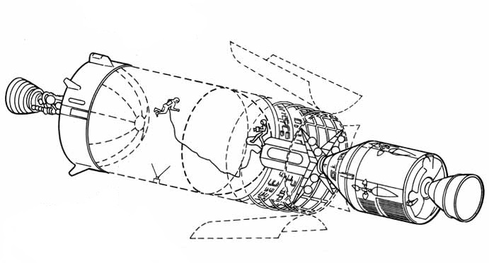
An S-IVB-derived Earth-orbital laboratory with an attached Spent-Stage Experiment Support Module (SSESM) and, at right, a docked, separately launched Apollo Command and Service Module (CSM). Image credit: NASA.

After reaching orbit, commands transmitted from the ground — or perhaps generated automatically by its attached IU — would cause the S-IVB to vent leftover propellants from its tanks. A second Saturn IB rocket would then launch a CSM with a crew of three. 

The astronauts would dock their CSM with the SSESM, which might contain equipment, life support consumables, and furnishings they could use to make the S-IVB LH2 tank into a habitable living and working space with 10,400-cubic-feet (295.5 cubic meters) of volume. Other plans for using of the S-IVB in Earth orbit saw the SSESM as the only pressurized volume; the LH2 tank would in that case provide an enclosed space for experiments performed in vacuum. The SSESM would include an airlock which space-suited astronauts could use to enter the LH2 tank.

The Douglas/IBM team called their proposed LASS program a "sequel" to the use of spent S-IVB stages in Earth orbit. The team anticipated that, after a development program spanning 45 months, the first automated LASS vehicle might deliver a 27,300-pound (12,380-kilogram) payload to the lunar surface and provide a "sheltered volume" on the Moon as early as the 1970-1971 period.

A LASS mission would begin with a Saturn V liftoff from a Launch Complex 39 pad at Kennedy Space Center, Florida. The rocket would comprise an unmodified S-IC first stage, an unmodified S-II second stage, and a modified S-IVB third stage — the LASS vehicle — with a payload on top under an aerodynamic nose cone. The Douglas/IBM team suggested that the 3200-pound (1450-kilogram) nose cone planned for Voyager automated Mars/Venus spacecraft launches might be repurposed for LASS launches.

Until the S-II stage shut down, LASS Saturn V ascent would closely resemble Apollo Saturn V ascent. In both cases, the S-II would separate from the spent S-IC stage two minutes and 41 seconds after liftoff at an altitude of 42 miles (68 kilometers) and ignite its five J-2 engines. The S-IVB or LASS vehicle would then separate from the S-II stage eight minutes and 40 seconds after liftoff at an altitude of about 109 miles (175 kilometers).

During Apollo missions, four forward-facing small retro-rocket motors on the tapered adapter linking the bottom of the 21.7-foot-diameter (6.6-meter-diameter) S-IVB with the top of the 33-foot-diameter (10-meter-diameter) S-II would fire immediately after S-II shutdown. This would slow the S-II slightly to facilitate S-IVB separation. The adapter, though considered part of the S-IVB, would remain attached to the S-II when the S-IVB separated. 

Small rocket engines on twin side-mounted Auxiliary Propulsion System (APS) pods would then fire to accelerate the S-IVB slightly. This would cause the weightless LH2 and LOX propellants within it to settle to the bottom of their tanks so that they could enter intakes leading to the S-IVB J-2 engine. The J-2 would then ignite to boost the S-IVB and its payload to low-Earth parking orbit. 

LASS vehicle launch configuration. Image credit: Douglas Aircraft Company/IBM.
Procedure for LASS vehicle landing leg deployment and separation from the Saturn V S-II stage. Image credit: Douglas Aircraft Company/IBM.
LASS vehicle engine and plumbing arrangement. Image credit: Douglas Aircraft Company/IBM.

LASS vehicle separation from the adapter linking it to the S-II stage would be more complicated. Four landing legs folded against the outside of the adapter under covers protecting them from aerodynamic heating during ascent would deploy, then a dozen forward-facing "ordinance thrusters" spaced 30° apart around top of the adapter would ignite to slow the S-II slightly to facilitate LASS vehicle separation.  

Replacing the four small retro-rockets on the Apollo Saturn V S-IVB/S-II adapter with 12 thrusters was necessary because the LASS vehicle included two RL-10 engines mounted on either side of its J-2 engine. Even with the RL-10 engine bells fully gimballed (pivoted) toward the J-2, LASS vehicle separation from the adapter using only the four retro-rockets would have been a risky business. Four thrusters would have meant less precision even if all worked as planned; in addition, the Douglas/IBM team estimated that if just one retro-rocket motor failed, collision between an RL-10 and the adapter was guaranteed.

The versatile RL-10 engine had been developed for the Centaur, the world's first LH2/LOX rocket stage. Combining throttleable RL-10 engines with Saturn hardware was nothing new when the Douglas/IBM team performed the LASS study; the Saturn I rocket, the first flightworthy member of the Saturn family, had mounted at the bottom of its S-IV second stage six RL-10s, each capable of producing 15,000 pounds (66,720 newtons) of thrust. 

First Saturn I launch: SA-1, 27 October 1961. Image credit: NASA.
Image credit: NASA.
Image credit: NASA.

Saturn I had been intended to launch astronauts into low-Earth orbit, but it was relegated to Apollo development flights without crews after NASA decided in 1962 that Saturn IB and Saturn V should become the Apollo launch vehicles. The last Saturn I flight, SA-10, launched a non-functional mass simulator ("boilerplate") Apollo CSM and the Pegasus III micrometeoroid detection satellite on 30 July 1965, a little more than three months before the LASS study commenced.

Use of the RL-10 as a LASS rocket engine was deemed necessary because the standard J-2 engine could not be throttled or gimballed enough to permit the LASS vehicle to land on the Moon. The Douglas/IBM team noted, however, that, if the proposed advanced J-2X engine were developed outside the LASS program — that is, without cost to the LASS development effort — then a single J-2X might replace the baseline J-2 engine and twin RL-10s. 

After successful LASS vehicle separation from the adapter and S-II, motors in its twin APS modules would fire to accelerate it slightly, causing the weightless propellants within it to settle to the bottom of their tanks. There they would enter intakes leading to the RL-10 and J-2 engines. 

The three engines would ignite to perform a single 8.5-minute Trans-Lunar Injection (TLI) burn that would expend 171,800 pounds (77,930 kilograms) of propellants to place the LASS vehicle on course for a 110-hour (4.5-day) voyage to the Moon. LASS vehicle mass would total 131,800 pounds (59,535 kilograms) at the end of the TLI burn. The LASS vehicle would then discard the aerodynamic nosecone covering its top-mounted payload.

The LASS TLI scheme was a significant departure from its Apollo counterpart. During Apollo lunar missions, the S-IVB J-2 would first burn for about 2.5 minutes, injecting it and the attached Apollo spacecraft into a 118-mile-high (190-kilometer-high) parking orbit about the Earth; then, about 2.5 hours after launch, it would burn again for about six minutes to depart parking orbit for the Moon. 

Loitering in parking orbit would permit a final checkout of Apollo spacecraft systems. Even more important, however, it would make available a daily launch window spanning several hours on each day of a monthly lunar launch window spanning several days. This flexibility would allow NASA to compensate for delays that might occur during the complex Saturn V pre-launch countdown.

The LASS vehicle's direct-ascent lunar mission profile would, by contrast, permit only a very brief launch window (in theory, it would be instantaneous). Direct-ascent, while worrisome from the standpoint of launching to any given lunar landing site during any given launch opportunity, would reduce the quantity of propellants expended to launch the LASS vehicle to the Moon. This would make available more propellants for two planned course corrections and for the all-important lunar landing burn.

Following the TLI burn, thrusters in the APS modules, governed by navigational electronics in the IU, would maneuver the LASS vehicle so that its three engines and the bottom of its LOX tank pointed at the Sun. This orientation would help to prevent the LASS vehicle's LH2 fuel from causing its LOX oxidizer to freeze. The RL-10 engines, meanwhile, would cyclically vent excess gaseous hydrogen that built up in the LH2 tank.

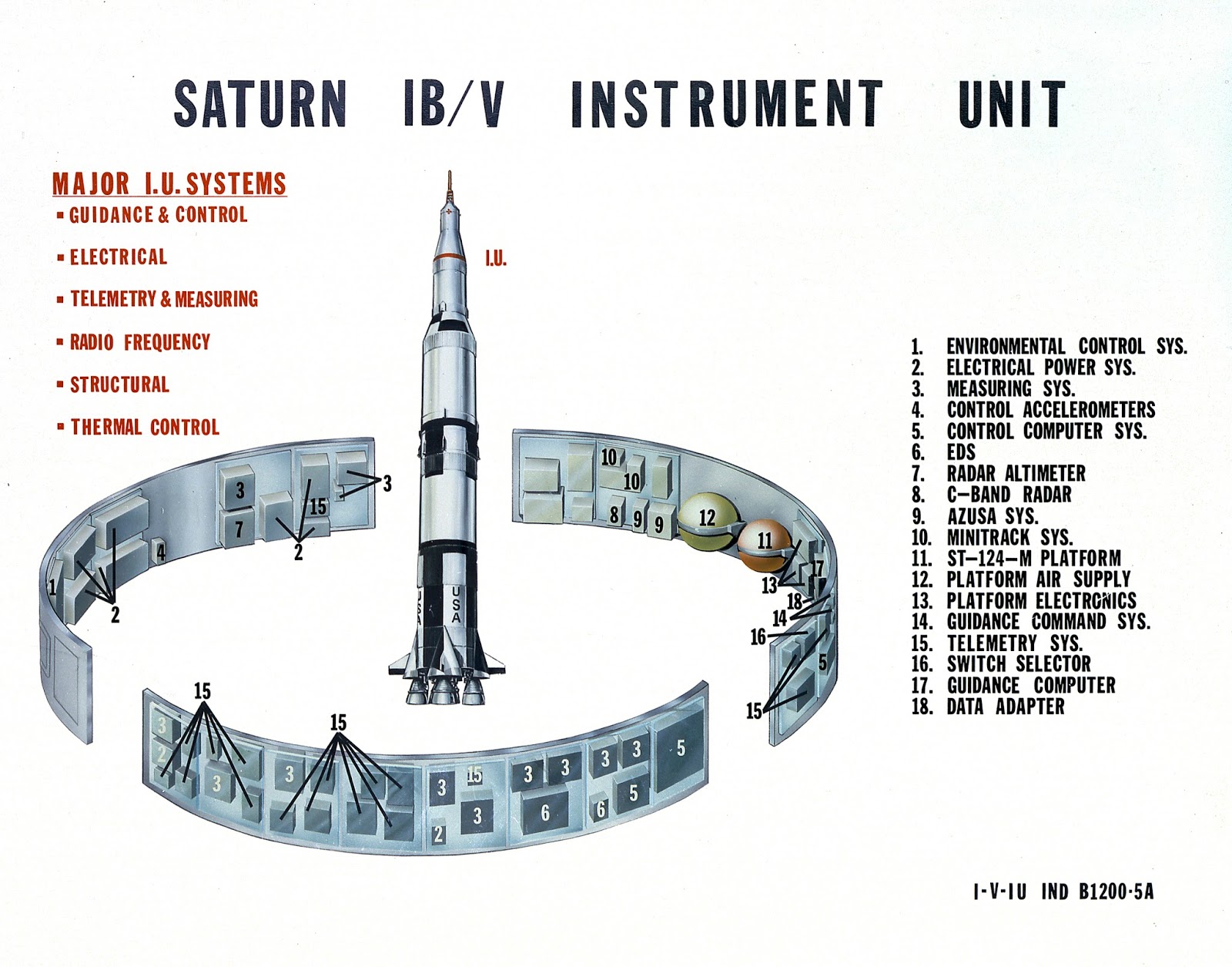
Technicians assemble an Instrument Unit (IU) at the IBM plant in Huntsville, Alabama. In their study, the Douglas/IBM team assumed that the interior walls and portions of the central area of the IU might be used to house new LASS vehicle systems. Image credit: NASA.
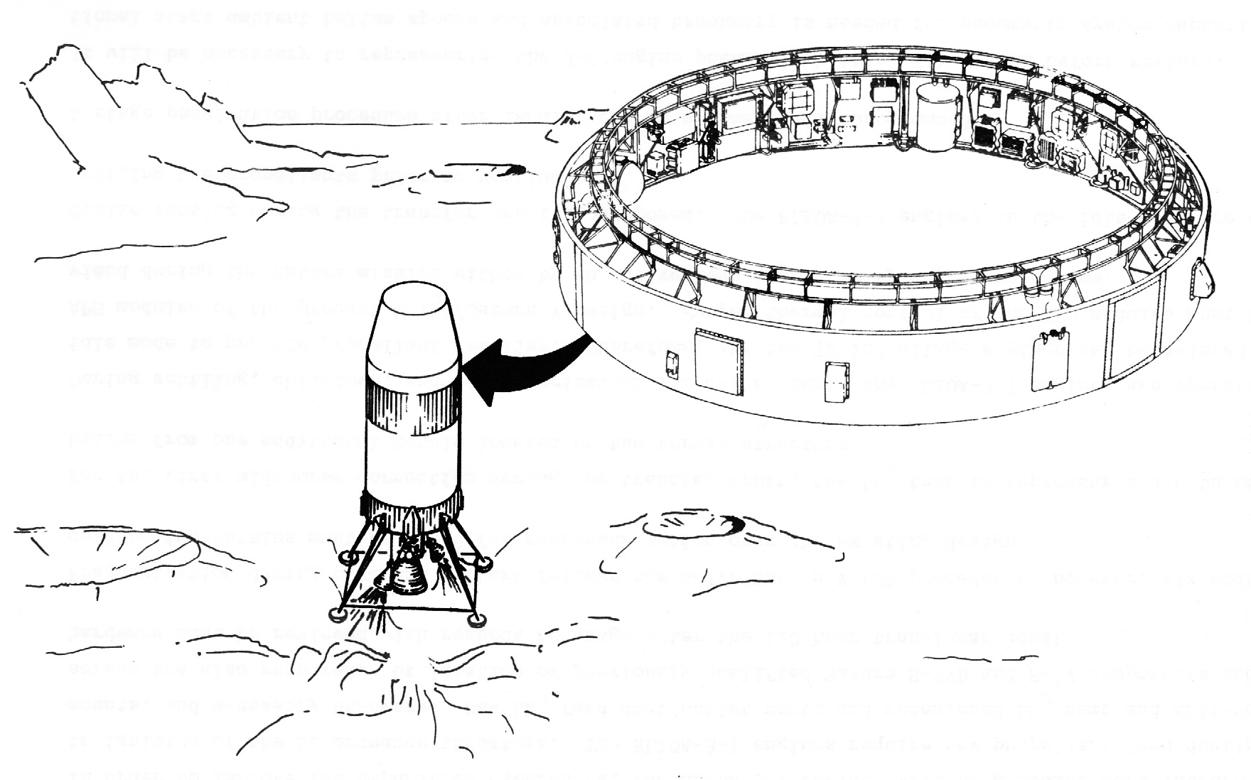
The LASS vehicle just before touchdown on the lunar surface. The illustration displays the position of the IU and, above it, the tapered LASS vehicle payload volume. Image credit: Douglas Aircraft Company/IBM.

The Douglas/IBM team considered the IU to be a candidate location for many new LASS vehicle systems. New navigation and communications systems, for example, would include long-range and short-range lunar landing radars, an altimeter, sensors for tracking the Sun, Earth, stars, and the lunar horizon, a data transmission system including a steerable high-gain dish antenna mounted on the outside of the IU, and a system for homing in on a pre-landed radio beacon at the target landing site on the Moon.  

Though the IU would include new navigational systems, it would still rely heavily on navigational data transmitted from Earth. The Douglas/IBM team expected that reliance on Earth-provided data — which would be generated using inputs from both Earth-based tracking and IU sensors — would ensure that the LASS vehicle could navigate successfully using 1966 state-of-the-art technology. Avoidance of new navigational systems would help to control LASS vehicle development cost.

The IU would also offer a candidate location for electricity-generating systems. These would include three Apollo CSM-type fuel cells, their thermal radiator, and tanks containing their LH2/LOX reactants, as well as rechargeable silver-zinc batteries for handling peak electrical demands during course corrections and the lunar landing burn. The fuel cells would provide three kilowatts of power continuously for the duration of the 110-hour LASS vehicle flight; the batteries would support peak loads of up to 6.76 kilowatts. 

Between 10 and 20 hours after launch, the LASS vehicle would perform its first course correction maneuver. The IU would orient the LASS vehicle for the burn using the APS thrusters, then would pressurize the LH2 tank and J-2 engine using helium drawn from spherical "bottles" mounted on the inner walls of the LH2 tank and on the thrust structure supporting the J-2 and RL-10 engines. 

The RL-10s, which could be ignited without propellant settling, would burn in "10% idle mode" to settle propellants so that they could reach the J-2 engine, then would throttle up as the J-2 ignited. After the three engines fired for a predetermined period of time, they would shut down and the IU would orient the LASS vehicle so that they would again point toward the Sun. If data supplied from Earth indicated that it was necessary, a second course correction would take place between 60 and 100 hours into the flight.

Unlike the Apollo CSM and LM spacecraft, the LASS vehicle would not inject into lunar orbit before descent to its target landing site. Instead, about 15,000 miles (24,140 kilometers) from the Moon and roughly 107 hours after liftoff, the Terminal Landing Phase (TLP) would commence. The IU would reorient the LASS vehicle so that its engines and four landing leg footpads pointed toward the Moon. At TLP start, LASS vehicle mass would total 117,500 pounds (53,300 kilograms).

About two hours later, at an altitude of about 450 miles above the Moon, the lunar horizon sensor would confirm LASS vehicle orientation. At an altitude of 350 miles, the IU would lock onto the signal from the pre-landed beacon at the landing site. The IU computer would begin performing TLP tracking calculations once per second. 

The RL-10 and J-2 engines would ignite to begin TLP Phase I braking at an altitude of 350,000 feet (160,680 meters). At 40,000 feet (12,190 meters), the altimeter would begin to supply data to the IU computer, supplementing beacon tracking data. 

TLP Phase II braking would begin with J-2 shutdown at 25,000 feet (7620 meters). At 10,000 feet (3050 meters), the IU would cease homing on the beacon. The IU computer would then very sensibly seek, as the Douglas/IBM team put it, to "drive all velocities relative to the surface to zero."

LASS vehicle landing legs and footpads. Image credit: Douglas Aircraft Company/IBM.

The IU would throttle the RL-10 engines to maintain a vertical descent velocity of 10 feet (three meters) per second and a lateral velocity of less than three feet (one meter) per second. When the IU-mounted short-range landing radar indicated an altitude of 70 feet (21.3 meters) above the Moon, the LASS vehicle's footpads would be about 10 feet (three meters) from the surface. The IU would then shut down the RL-10s and the LASS vehicle would drop the remaining distance. 

The Douglas/IBM team judged that their TLP system could enable a touchdown within 500 feet (150 meters) of the pre-landed beacon. LASS vehicle mass at touchdown would total 63,580 pounds (28,840 kilograms). Of this, payload above the IU would total up to 27,300 pounds (12,380 kilograms). 

Immediately after touchdown, the IU would command the LASS vehicle to "passivate" itself. The Douglas/IBM team did not describe the passivation process in any detail, though its aim would be to evacuate vessels containing liquids and gases that might freeze, leak, or over-pressurize and burst their containers. For example, about 2000 pounds (910 kilograms) of leftover LH2 and LOX propellants in the LASS vehicle tanks would be vented overboard. Gases and liquids in the payload would, of course, be immune from passivation.

After an unspecified period of time, astronauts would land near the LASS vehicle in an Apollo LM. The Douglas/IBM team provided few details about how the crew would interact with the LASS vehicle. They offered only a few vague suggestions concerning, for example, how astronauts in bulky space suits might ascend the approximately 60 feet (18.3 meters) to the top of the LASS vehicle to reach the payload. Neither did they describe how payload items would be moved from the top of the LASS vehicle to the surface, though they suggested that unspecified "cargo & handling equipment" with a mass of 3100 pounds (1400 kilograms) would be available. These and other mysteries would no doubt have been addressed if NASA had opted to fund additional LASS studies.

The Douglas/IBM engineers did, however, define five typical LASS payload configurations and mission durations. All would feature lunar exploration hardware under consideration in 1966 for AAP lunar missions and would see IU navigational and communications electronics serve double-duty as experiment data support equipment.

Configuration 1 was most in keeping with the role of the LASS vehicle as a sequel to an S-IVB-derived laboratory in low-Earth orbit. The LASS vehicle's LH2 tank would be lined with 3940 pounds (1785 kilograms) of micrometeoroid shielding and thermal insulation before launch from Earth; this weight would be subtracted from the weight available for payload above the IU. 

About 7700 pounds (3490 kilograms) of the payload above the IU would take the form of a two-man shelter similar to the SSESM proposed for the Earth-orbiting S-IVB laboratory. Life support gases and liquids and other expendables would account for 4500 pounds (2040 kilograms) of the payload. Experiment apparatus with a total weight of 500 pounds (227 kilograms), a 1000-pound (454-kilogram) unpressurized Lunar Scientific Survey Module (LSSM) rover, and a one-or-two-person Lunar Flying Unit (LFU) of unspecified weight would make up the balance of the payload.

LASS vehicle candidate lunar surface payload: Lunar Scientific Survey Module (LSSM) rover. Image credit: NASA.
LASS vehicle candidate lunar surface payload: Lunar Flying Unit. Image credit; Bell Aerospace.

Configuration 1 would see the two astronauts lower themselves into the LASS vehicle LH2 tank by unspecified means through an airlock in the shelter. The LH2 tank would then serve as either a laboratory or an emergency shelter. The crew would live in the LASS vehicle for up to 14 days before they reactivated their LM and returned to the Apollo CSM waiting in lunar orbit.

The other four LASS payload configurations would not make use of the LH2 tank, so the weight of the shielding and insulation surrounding it in Configuration 1 could be applied to payload above the IU. Configuration 2, with a 30-day lunar surface stay time, would include a 13,000-pound (5900-kilogram) four-man shelter, a 3800-pound (1725-kilogram) small (though possibly pressurized) rover, 4500 pounds (2040 kilograms) of science equipment, and 5700 pounds (2585 kilograms) of expendables. The Douglas/IBM team did not explain how four astronauts could reach the LASS vehicle on the Moon using the three-man CSM and two-man LM. 

Configuration 3 would include a four-man shelter, an LSSM, science equipment, and 8500 pounds (3855 kilograms) of expendables. The four-person crew would remain on the Moon for 59 days. Configuration 4 would include a two-person shelter, a small rover, scientific equipment, and 11,000 pounds (4990 kilograms) of expendables. The crew would evenly divide their time during their 120-day lunar surface stay between the shelter and the small rover. Configuration 5 would include a two-person shelter, an LSSM, scientific equipment, and 13,800 pounds (6260 kilograms) of expendables. The crew would evenly divide their time during their 195-day stay between the shelter and the LSSM. 

The Douglas/IBM team suggested that the astronauts might tip the roughly 60,000-pound (27,215-kilogram) LASS vehicle on its side to place its payload above the IU — which in this case would not include a shelter — close to the lunar surface. They did not, however, explain how the astronauts might accomplish this feat. They suggested that the crew could live inside their LM while they unloaded equipment from the tipped LASS vehicle and converted its LH2 tank into a shelter. 

A LASS vehicle with more extensive modifications — for example, a large rectangular hole cut into its LH2 tank for mounting a telescope — might be tipped on its side and converted into a lunar surface astronomical observatory. Ultimately, multiple upright and tipped LASS vehicles might be dragged together to form a "LASS Modular Lunar Base." The Douglas/IBM engineers ended their report by declaring that "LASS is envisioned to be the vehicle to support all lunar surface programs." 

During the 1960s, Douglas, IBM, and other contractors studied other new roles for the S-IVB and IU. These included a lunar-orbital lab, a testbed for reusable single-stage-to-orbit vehicles, a communications relay supporting missions to the Moon's farside hemisphere, a delivery vehicle for multiple automated lunar landers based on the Apollo LM descent stage, a testbed for interplanetary heat shield tests, and an interplanetary booster for automated and piloted spacecraft. Some of these are described in the "More Information" section below. Others will be described in future posts.

Sources

"NASA Launch Vehicles," Aviation Week & Space Technology, 2 July 1962, p. 91.

"Rendezvous to Slash Apollo Target Time," Aviation Week & Space Technology, 2 July 1962, pp. 106-111.

"Marshall Supervises Booster Development," Aviation Week & Space Technology, 2 July 1962, pp. 113-125.

Lunar Orbit Rendezvous — News Conference on Apollo Plans at NASA Headquarters on July 11, 1962, News Release and Press Conference Transcript, NASA, 1962.

Lunar Applications of a Spent S-IVB/IU Stage (LASS), presentation by Douglas Aircraft Company Missile & Space Systems Division and International Business Machines Federal Systems Division, September 1966.

"NASA Adapting S-4B for Space Station," W. Normyle, Aviation Week & Space Technology, 5 September 1966, p. 34.

"Manned Lunar Program Options Mission Modes," TM-67-1012-5, C. Bendersky & D. R. Valley, Bellcomm, Inc., 5 May 1967, pp. 9-10.

"Lunar Applications of a Spent S-IVB/IU Stage (LASS)," Douglas Paper No. 4256, L. O. Schulte & D. E. Davin, Douglas Missile & Space Systems Division; paper presented at the American Institute of Aeronautics and Astronautics Fourth Annual Meeting and Technical Display in Anaheim, California, 23-27 October 1967.

Stages to Saturn: A Technological History of the Apollo/Saturn, NASA SP-4206, Roger Bilstein, 1980, pp. 58-85, 129-153, 157-190, 241-257, 323-329, 336-345, 414-415.

More Information

One-Man Space Station (1960)

Space Station Gemini (1962)

Space Station Resupply: A 1963 Plan to Turn the Apollo Spacecraft Into a Space Freighter

Re-Purposing Mercury: Recoverable Space Observatory (1964)

"Still Under Active Consideration": Five Proposed Earth-Orbital Apollo Missions for the 1970s (1971)

Evolution vs. Revolution: The 1970s Battle for NASA's Future

Talking to the Farside: A 1963 Proposal to Use the Apollo Saturn V S-IVB Stage as a Radio Relay

Relighting the FIRE: A 1966 Proposal for Piloted Interplanetary Mission Reentry Tests

NASA's Planetary Joint Action Group Piloted Mars Flyby Study (1966)

"Without Hiatus": The Apollo Applications Program in June 1966

The First Voyager (1967)

A Year in Orbit Using Apollo Technology: Command and Service Module for Longevity (1966)

The Skylab 2 Command and Service Module sits atop its Saturn IB launch vehicle on Pad 39B at NASA Kennedy Space Center, Florida. The spacecraft, with astronauts Charles Conrad, Paul Weitz, and Joseph Kerwin on board, lifted off on 25 May 1973, docked with the Skylab space station, and returned to Earth on 22 June 1973. Image credit: NASA.
The Apollo Command and Service Module (CSM) was the work-horse U.S. piloted spacecraft from its first launch in October 1968 until its last Earth-atmosphere reentry and splashdown in July 1975. Launched atop two-stage Saturn IB and three-stage Saturn V launch vehicles, it carried six three-man crews to low Earth orbit and nine to lunar orbit. These missions saw it operate twice on its own, nine times with Apollo Lunar Module (LM) landers, three times with the Skylab Orbital Workshop, and once with a Docking Module and a Soviet Soyuz spacecraft.

At mission's end, just prior to reentry, the CSM split into two parts. The conical Command Module (CM) included a bowl-shaped reentry heat shield, a pressurized crew compartment with couches and controls, lithium hydroxide canisters for removing from its pure oxygen cabin air carbon dioxide exhaled by its crew, a nose-mounted docking system, reentry reaction control rocket engines, reentry batteries, and parachutes in a nose-mounted compartment. 

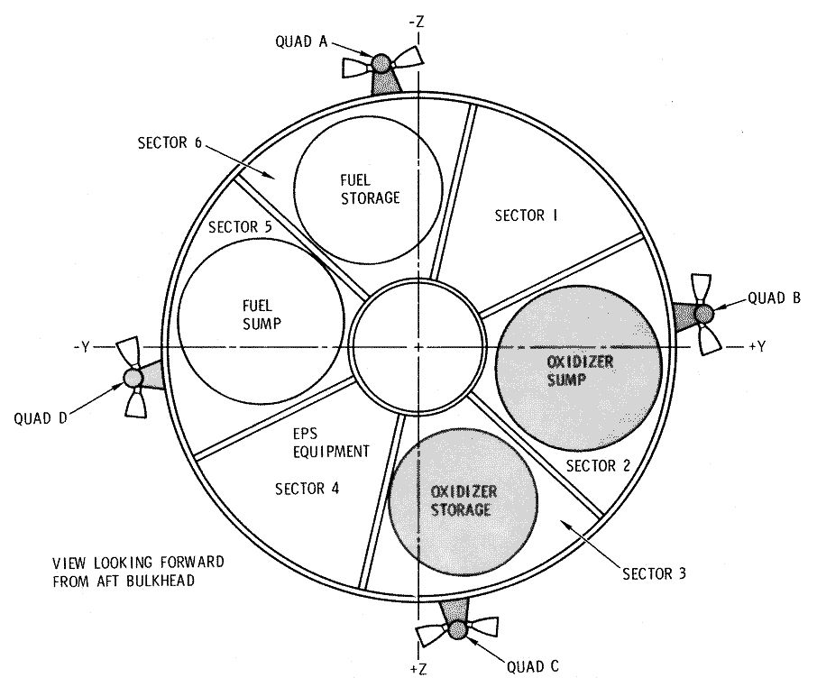
The largest part of the CSM, the drum-shaped Service Module (SM), included in six internal "sectors" and a cylindrical central section three fuel cells for making electricity and water, radiators, four clusters of reaction control rocket engines, the Service Propulsion System (SPS) main engine, and tanks containing cryogenic liquid hydrogen/liquid oxygen fuel cell reactants, helium pressurant, and hypergolic (ignite-on-contact) propellants. The SM provided the CM with electricity, oxygen, water, thermal control, propulsion, attitude control, and (when required) a long-range radio link to Earth. 

After the two modules separated, the SM was destroyed in Earth's atmosphere. The CM, meanwhile, descended on its deployed parachutes to an ocean splashdown.

Block II Apollo CM cutaway. Image credit: NASA.
Block II Apollo SM cutaway. Image credit: NASA.

Apollo CSMs might have flown many more missions had NASA's Apollo Applications Program (AAP) gone ahead as planned in 1965-1966. As described elsewhere in this blog (see "More Information" below), AAP aimed to exploit Apollo spacecraft and Saturn rocket hardware developed for the Moon program to accomplish new things in space at reduced cost. It emphasized three major themes: science experiments, including many of potential benefit to people on Earth; advanced lunar exploration featuring long lunar surface stays with enhanced mobility; and long-duration Earth-orbital flights. 

AAP, which was originally intended to span from 1968 through 1972, was proposed by NASA and endorsed by President Lyndon Baines Johnson, but some within Congress, NASA, and the aerospace industry had mixed feelings about it. Some saw it as a "make-work" program; a subset of those believed that NASA should aspire to objectives greater than mere repurposing of Apollo and Saturn hardware. Olin Teague, the chair of the House Space Subcommittee and a champion of the NASA Manned Spacecraft Center (MSC) in Houston, Texas, went so far as to call the Johnson Administration "derelict" in establishing a post-Apollo goal for NASA.

At the same time, the U.S. military commitment in Indochina was expanding rapidly, making many members of Congress uneasy about funding new space projects — even when those projects aimed to economize by repurposing space technology already developed. 

By June 1966, it had become abundantly clear that Congress would not fund AAP in Fiscal Year 1967 at the level the Johnson Administration had requested. Against that inauspicious backdrop, William Hough, an engineer with Bellcomm, NASA's Washington DC-based planning contractor, commenced a study of a low-cost, low-complexity long-duration AAP mission. 

Hough aimed to determine whether NASA could, through minimal upgrades of Apollo lunar program hardware, keep one, two, or three astronauts in low-Earth orbit continuously for a year. A one-year stay would lay the biomedical groundwork for more ambitious space missions — a large permanent Earth-orbital laboratory was high on the list — beginning in the mid-to-late 1970s. 

In a 21 July 1966 technical memorandum, Hough described a spacecraft he called the CSM for Longevity (CSML), which would be derived from the Block II CSM planned for Apollo missions to the Moon. The CSML would tap advanced Apollo technology that engineers at North American Aviation (NAA), the CSM prime contractor, had studied for use in an Extended CSM (XCSM) design. NAA described its XCSM in the multi-volume Final Report, Preliminary Definition Phase: Apollo Extension System, which they completed in December 1965-January 1966. The company prepared the XCSM report on contract to NASA MSC.

The CSML would operate with a Dependent Experiment Support Module (DESM), which might, Hough wrote, be based on any of the several Apollo-derived laboratory modules proposed for AAP or "a module as yet undefined." In mid-1966, candidate AAP lab modules included a stripped-down Apollo LM with or without a Descent Stage (the "LEM Lab"), a refurbished flown Apollo CM, and a drum-shaped Spent Stage Experiment Support Module (SSESM) attached to an S-IVB Saturn rocket stage. Regardless of the form the DESM took, it would rely on the CSML for electricity, life support, thermal control, and propulsion. This would, Hough explained, permit the lab module to be devoted entirely to experiments.

Candidate DESM: LEM Lab. A CSM is shown docked to provide a sense of scale. Image credit: NASA.
Candidate DESM: two designs for a refurbished flown CSM. Image credit: NASA.

Candidate DESM: Spent Stage Experiment Support Module (SSESM) and S-IVB stage. A CSM is shown docked to provide a sense of scale. Image credit: NASA.

At the start of the one-year mission a CSML bearing a crew of three would lift off from Cape Kennedy, Florida, and ascend to a 148.2-kilometer (80-nautical-mile) low-inclination interim Earth orbit either by itself atop a Saturn IB or atop a Saturn V with the DESM. If the CSML reached Earth orbit on a Saturn IB, the DESM would be launched separately to interim orbit atop a second Saturn IB.

Drawing on July 1966 data, Hough estimated that the maximum weight a Saturn IB could deliver to interim orbit was 17,100 kilograms (37,700 pounds). He set this as the upper boundary of CSML weight at launch.

In the Saturn IB-launched case, the CSML would rendezvous with the DESM attached to the top of the spent S-IVB second stage of the Saturn IB that launched it then would dock with the DESM. In the Saturn V-launched case, the CSML would detach from the Saturn V's spent S-IVB third stage, turn end for end, and dock with the DESM attached to the top of S-IVB. 

If the Saturn V-launched DESM were based on the LM or a refurbished CM, the CSML crew would detach it from the spent S-IVB. If the DESM were an SSESM/S-IVB stage, on the other hand, the CSML crew would enter the SSESM and vent leftover liquid hydrogen and liquid oxygen propellants from the S-IVB stage so that its 6.7-meter-diameter (21-foot-diameter) hydrogen tank could serve as a laboratory. In any case, after they checked out and prepared the DESM the crew would fire the CSML SPS main engine to boost the CSML/DESM combination to a 370.4-kilometer (200-nautical-mile) low-inclination operational orbit. 

A single CSML could not carry enough consumables to support a three-man crew in orbit for a year, so resupply CSMLs identical to the first CSML would be launched periodically atop Saturn IB rockets. "Resupply" was something of a misnomer, for no supplies would be transferred to the CSML/DESM combination already in orbit. 

Instead, as few as one or as many as three astronauts on board the CSML/DESM would spacewalk to swap places with an equal number of astronauts newly arrived in the resupply CSML. After the swap, the astronauts in the nearly spent CSML attached to the DESM would undock to return to Earth while those in the fresh resupply CSML would dock with the DESM so that the astronauts who transferred from the nearly spent CSML could continue their one-year mission. 

Even as Hough began his study, NASA launched Gemini IX (3-6 June 1966). A day into the mission astronaut Eugene Cernan performed the second U.S. spacewalk. Because he lacked adequate handholds and footholds and had to fight his suit's internal pressure to bend his arms and legs, Cernan became dangerously overheated. He was unable to test a U.S. Air Force-built Astronaut Maneuvering Unit backpack as planned. NASA was soon forced to rethink its approach to spacewalking. Though his one-year mission plan would rely heavily on spacewalks, Hough made no reference to Gemini IX in his memorandum. 

During the Apollo 9 mission (3-13 March 1969) astronauts David Scott (pictured) and Russell Schweickart performed spacewalks outside the CSM Gumdrop (lower left) and the LM Spider (upper right) in low-Earth orbit. Had Hough's plan for a year-long CSML mission gone ahead, a scene similar to this might have taken place during crew exchange between a CSML/DESM combination and a newly arrived resupply CSML. Image credit: NASA.

Much of Hough's report was devoted to determining the number of CSMLs needed for a one-year stay in space by at least one astronaut. Not surprisingly, this would depend on expected CSML endurance. At the "lower bound of technological sophistication" was a minimal CSML with an orbital endurance of just 35 to 40 days. This meant that NAA's XCSM, which was rated for 45 days, could easily do the job. 

Using the XCSM would, however, mean that a one-year stay would require about 12 launches. Hough rejected this approach because it would need more Saturn rockets and Apollo spacecraft than NASA expected to have available each year for the AAP.

Hough described changes to the Block II Apollo CSM required to turn it into a CSML capable of operating in orbit without replacement for 94 days (in which case four CSMLs would enable a year-long stay) or 125 days (in which case three CSMLs would suffice). CM modifications would be relatively minor while SM modifications would be extensive.

The most significant CM modification in terms of weight impact would be replacement of the Block II Apollo lithium hydroxide carbon-dioxide removal system — except for a two-day emergency supply of canisters — with a "two bed, thermal swing, vacuum-dump molecular sieve" system. The twin chemical beds would alternate; that is, one bed would be opened to absorb carbon dioxide from the CSML cabin air while the other would be closed off, exposed to the vacuum of space, and heated to drive out the carbon dioxide it had absorbed. 

Unlike the Apollo Block II CSM, the CSML would include nitrogen in its cabin air. Introduction of nitrogen was a concession to space life scientists who worried about long astronaut exposure to pure oxygen. Nitrogen would be stored in the SM, so CM weight changes resulting from the new air mix would be minimal.

Hough missed few details. He noted, for example, that the CM parachute compartment would gradually lose pressure during a long space stay, and that the vitally important parachutes it contained could be damaged if exposed to vacuum. He proposed placing nine kilograms (20 pounds) of solid "vaporizing material" of unspecified composition in the compartment. This would slowly turn to gas, keeping the pressure level in the compartment steady. 

Most of Hough's study consisted of finding tradeoffs to keep CSML weight below the 17,100-kilogram (37,700-pound) limit. The most important of these tradeoffs was deletion of propulsion capability in favor of added electricity-generation capability. 

He calculated that just 1633 kilograms (3600 pounds) of hydrazine fuel and nitrogen tetroxide oxidizer would be sufficient to carry out all major maneuvers required of the SPS main engine: specifically, boosting the CSML/DESM from its interim orbit to its operational orbit; resupply rendezvous with the CSML/DESM combination in operational orbit; and deorbiting the CSML at the end of its long stay in orbit. The amount of propellant required for these maneuvers would be the same regardless of the duration of the CSML mission.

This quantity of SPS propellants totaled less than 10% of the SPS propellant capacity of the Block II Apollo CSM. A pair of new, shorter SPS propellant tanks in sectors 2 and 5, measuring 1.3 meters (4.25 feet) in diameter by just 22.9 centimeters (9 inches) tall, would, Hough calculated, suffice to contain this quantity of propellants. That would free up most of sectors 2, 3, 5, and 6 and the central cylindrical compartment for fuel cell reactants and other consumables. 

Block II Apollo CSM sector layout. Image credit: NASA.

The small amount of orbit maintenance propulsion required to avoid orbital decay during a long mission would, Hough wrote, be provided by the four Reaction Control System (RCS) thruster quads spaced evenly around exterior of the SM. The RCS would expend an average of about nine kilograms (20 pounds) of hydrazine fuel and nitrogen tetroxide oxidizer per day to maintain the CSML's orbital altitude and control its attitude, bringing the total RCS propellant load to about 846 kilograms (1880 pounds) for a 94-day CSML and about 1125 kilograms (2500 pounds) for a 125-day CSML. This would require expansion of the RCS tanks.

Hough proposed that four advanced "asbestos-membrane" fuel cells replace the three "Bacon-cell" fuel cells housed in sector 4 of the Block II Apollo SM. The latter were rated to operate for 400 hours (16.7 days), which was ample time to complete an Apollo lunar mission. He reported that a test version of the asbestos-membrane fuel cell had operated continuously for 1200 hours (50 days) and that it was expected to be capable of operating for up to 2500 hours (104.2 days). 

Asbestos-membrane fuel cells featured a handy in-flight start capability, Hough explained, permitting them to be operated in shifts to extend CSML orbital lifetime and increase redundancy. He envisioned that one or two would remain on "cold standby" at any one time. He calculated that two could produce three kilowatts of electricity continuously if they consumed an average of 1.23 kilograms (2.72 pounds) of liquid hydrogen/liquid oxygen reactants per hour. Three kilowatts was approximately double the amount of electricity needed for routine CSML "housekeeping" functions, thus making available about 1.5 kilowatts for DESM experiments. 

It is fair to ask why Hough did not consider systems other than fuel cells for generating CSML electricity. The Bellcomm engineer might have proposed that the CSML rely on solar arrays or an isotopic system, either of which would be less massive than fuel cells and heavily insulated tanks of cryogenic reactants. He explained that neither solar arrays nor a nuclear system had not been studied for use in XCSM missions, so they could not be considered to be within the bounds of Apollo technology as he defined them in his study. 

Hough acknowledged that, in spite of careful tradeoffs, his year-long mission tended toward tight consumables margins. For example, he allotted just three days of overlap for each resupply mission. This meant that "a few days of hurricane watch at KSC at the time of a resupply launch would cause termination of the total mission."

Though he studied it carefully, Hough was not especially enthusiastic about the CSML/DESM approach to a one-year mission. He explained that "it is probable that the CSML/DESM is not the best approach when compared to the self-sufficient new module" approach, though he maintained that "it appears to be optimum if the constraint of use of Apollo technology. . .is imposed." 

Hough argued that the main reason to settle for the CSML/DESM approach — aside from "a possible lean year or two of spacecraft launches" caused by AAP funding cuts — would be the appearance of new information concerning "man's compatibility with long-term spaceflight" that made the viability of long astronaut stays on board a self-sufficient module seem doubtful. In that case, attempting a one-year CSML/DESM mission to gain additional data ahead of a large investment in a new module might be seen as frugal.

He added that, if sufficient resources existed for both a one-year CSML/DESM mission and development of a self-sufficient module, then the CSML/DESM mission could be seen as a prudent step forward even if the viability of long-duration spaceflight were assured. Experiments in the DESM might include a prototype advanced power source independent of the CSML's fuel cells or test versions of long-duration life support systems. 

In August 1966, NASA took a step toward a "self-sufficient new module" when it opted to focus its Earth-orbital AAP efforts on the SSESM/spent S-IVB stage laboratory option. The space agency renamed the SSESM the Airlock Module; the spent S-IVB stage became known as the Workshop. In the Airlock Module/Workshop scenario, the CSM would serve mainly as a crew transport; the Airlock Module/Workshop would include independent life support and electricity-generating systems.

Apollo 9 CSM Gumdrop in low-Earth orbit as viewed from the LM Spider, March 1969. Image credit: NASA.

Sources

"Gemini 9 Underscores Knowledge Gaps," Aviation Week & Space Technology, 11 July 1966, p. 37.

"CSM Configuration Study for One Year Mission to be Achieved by Rendezvous and Resupply," W. W. Hough, Bellcomm, Inc., 21 July 1966.

"Washington Roundup — Apollo Roller Coaster," Aviation Week & Space Technology, 1 August 1966, p. 15.

"NASA Post-Apollo Plan Urged by Dec. 1," George C. Wilson, Aviation Week & Space Technology, 8 August 1966. pp. 26.

Skylab: A Chronology, NASA SP-4011, Roland W. Newkirk and Ivan D. Irtel with Courtney G. Brooks, NASA Scientific and Technical Information Office, 1977, p. 88.

More Information

Apollo Extension System Flight Mission Assignment Plan (1965)

Apollo Applications Program: Lunar Module Relay Experiment Laboratory (1966)

"Without Hiatus": The Apollo Applications Program in June 1966

NASA's Planetary Joint Action Group Piloted Mars Flyby Study (1966)

Robotic flyby: encapsulated in a streamlined shroud, the Mars-bound Mariner IV spacecraft awaits launch from Florida atop an Atlas-Agena rocket. Image credit: NASA.
The piloted Mars/Venus flyby concept — the hallmark of which was a Sun-centered trajectory intersecting one or more planets and beginning and ending at Earth — was first proposed by Gaetano Crocco in 1956, at a time when robotic probes to other worlds were scarcely mentioned by champions of spaceflight. A decade later, when NASA performed its first high-level NASA-wide study of the piloted flyby concept, that situation had changed markedly — thanks largely to a 261-kilogram (575-pound) spacecraft called Mariner IV.

Launched on 28 November 1964, Mariner IV demonstrated for the first time that a robotic spacecraft could return useful data from the vicinity of Mars. The success of Mariner IV — it captured 21 images of the planet as it flew past on 15 July 1965, and slowly transmitted them to Earth over the following month — gave ammunition to those who called into question the utility of piloted flybys. 

The Mariner IV images revealed a cratered, arid surface, and its radio occultation experiment found an atmosphere only 1% as dense as Earth's. Mars, seemingly so promising for the development of life, suddenly appeared almost as inhospitable as Earth's barren Moon. 

Supporters of Mars exploration were quick to point out, however, that the little spacecraft had imaged only about 1% of Mars at a resolution so low that, had it flown past Earth, it would not have found life. NASA and the planetary science community persisted with plans to launch new scientific exploration missions to Mars in the Mariner and Voyager programs (the latter not to be confused with the late 1970s Voyager originally called Mariner Jupiter-Saturn — please see "More Information," below). 

Cratered planet: One of the sharpest Mariner IV images of Mars. Image credit: NASA.
In like fashion, piloted flyby proponents — such as the participants in the Planetary Joint Action Group (JAG), led by Edward Z. Gray of the NASA Headquarters Office Manned Space Flight (OMSF) — proceeded with their planning meetings in spite of Mariner IV's achievement. The first Planetary JAG meeting, held at the NASA Manned Spacecraft Center (MSC) in Houston, Texas, on 4 May 1966, gave roughly equal priority to piloted Mars/Venus flybys and a piloted Mars landing mission. 

By the Planetary JAG's second meeting, held at NASA Headquarters in Washington on 9 June 1966, piloted flybys had assumed primacy. "The object of the effort," the Group declared, "is a Mars/Venus Fly-by capability by [19]75 with a manned Mars landing in view." 

Ironically, given the negative effect of Mariner IV, a new class of robotic probe was largely responsible for the positive change in the piloted flyby concept's fortunes. The Mars Surface Sample Returner (MSSR), first discussed at the NASA Headquarters meeting, would borrow technology and experience from Mariner and Voyager. It would ride to Mars on board the piloted flyby spacecraft. After carefully checking out and servicing its systems, the crew would release it several days before the flyby. It would reach Mars hours ahead of the flyby spacecraft, land, collect samples of martian air and dirt, and launch them into space. 

The astronauts would capture the sample container minutes after their closest approach to Mars. They would analyze the sample in a lab on board the piloted flyby spacecraft within an hour of its launch from Mars, before any living things it contained could perish. 

More than 50 engineers from across NASA attended the Planetary JAG's third meeting at NASA Kennedy Space Center (KSC) on 29-30 June 1966. By then, the Group had begun work on a pair of documents: a briefing to the high-level managers of the NASA Management Council and a preliminary Program Development Plan (PDP). Bellcomm, NASA's Washington, DC-based planning contractor, provided the Group with technical assistance.

The briefing took place a month later — the Council's response is not recorded, but it was apparently favorable enough for work on the PDP to continue. The completed PDP, labelled "For Internal Use Only," bore the date 3 October 1966. 

The Planetary JAG envisioned that the 1975 Mars flyby, launched out of low-Earth orbit between 5 September and 3 October of that year, would be the first in a series of four Mars and Venus flyby missions. It would last 667 days. The other three were a 715-day Venus/Mars/Venus flyby mission launched in February 1977, a 625-day Venus/Mars flyby mission launched in December 1978, and a 686-day Mars flyby mission launched in November 1979. Regardless of the number of flybys it contained, no piloted flyby mission would require more than modest course-correction propulsion after departure from low-Earth orbit. 

Only the 1975 mission was described in detail in the PDP. It would follow a low-energy twilight trajectory that would take it past Mars and would reach aphelion — its greatest distance from the Sun — on the inner edge of the Asteroid Belt, at 2.2 times the Earth-Sun distance. The term "twilight" referred to the Mars pass geometry; flyby spacecraft Mars periapsis (closest approach) would occur over the line separating the dayside from the nightside. 

Seven years of development and testing would precede launch of the 1975 mission. The flyby program nested within a series of extant and anticipated NASA programs and missions, which the Planetary JAG stated provided "a sound base for the development of a manned flyby system." The piloted flyby spacecraft, for example, would be based on hardware and experience from Apollo and its planned follow-on, the Apollo Applications Program (AAP). Set to begin as early as 1968, AAP was envisioned primarily as an Earth-orbital space station program, but was also expected to include "limited lunar exploration" beyond the Apollo baseline.

AAP astronauts would carry out progressively longer missions on board Orbital Workshops, achieving a one-year stay in weightlessness in 1970 or 1971. The AAP Orbital Workshop would take the form of a converted S-IVB stage, which formed the second stage of the Saturn IB rocket and the third stage of the Saturn V. A third Orbital Workshop launched in 1972-1973 would test prototype piloted flyby spacecraft subsystems.

Major components of the Planetary JAG's piloted flyby spacecraft. A = Propulsion Module (PM) with toroidal propellant tanks and four engines; B = Apollo-derived Earth-Entry Module (EEM) with heat shield tunnel; C = Mission Module (MM) with tunnel to airlock/biological laboratory; D = Experiment Module (EM) with MSSR probe, airlock, telescope, and biological laboratory (probe complement illustrated differs from that described in Planetary JAG PDP); E = deployed high-gain antenna (stowed position also shown); F = deployed solar array. 
In the same timeframe, robotic precursor probes would provide important data to engineers designing piloted flyby mission systems. A Mariner spacecraft would release a probe to plumb the martian atmosphere in 1971 and possibly again in 1973 and probes would assess the meteoroid population between the orbit of Venus and the inner edge of the Asteroid Belt in 1970 or 1971. The former would aid in piloted flyby probe design and the latter might permit reduced piloted flyby spacecraft meteoroid shielding. Weight saved by reducing shielding might permit a heavier scientific payload on board the piloted flyby spacecraft.

Late 1972 would see a test of a Earth Entry Module (EEM) derived from the Apollo Command Module design but capable of withstanding Earth-atmosphere reentry at the end of the piloted flyby mission at up to 50,000 feet per second — that is, 14,000 feet per second more than the maximum planned Apollo lunar-return speed. In 1973-1974, four astronauts — the number planned for the piloted flyby spacecraft crew — would rehearse the piloted flyby mission for a year in low-Earth orbit on board a prototype 180,000-pound (81,650-kilogram) piloted flyby spacecraft. They would ride to Earth orbit and return to Earth in a 51,500-pound (23,350-kilogram) CSM launched with the flyby spacecraft.

The S-IVB stage was the third stage of the Saturn V rocket (shown in silhouette at left) and the second stage of the Saturn IB rocket. It was tapped as the structural basis of the AAP Orbital Workshop. The Planetary JAG expected that three Modified S-IVB stages launched on two-stage Saturn Vs would boost piloted flyby spacecraft out of Earth orbit toward Mars and Venus. Image credit: NASA.
The piloted flyby spacecraft and CSM would reach Earth orbit atop a two-stage "Improved" Saturn V rocket, the workhorse launch vehicle of the piloted flyby program. The Improved Saturn V would comprise an S-IC first stage stretched 20 feet (6.6 meters) to hold additional propellants for its beefed-up F-1 engines. In addition to launching the piloted flyby spacecraft and CSM, it would be used to rapidly launch a series of three 231,400-pound (105,000-kilogram) Modified S-IVB (MS-IVB) stages which would link up with the piloted flyby spacecraft in 485-kilometer (300-mile) assembly orbit to form an Orbital Launch Vehicle (OLV). 

The MS-IVB stages would each contain 195,800 pounds (88,800 kilograms) of cryogenic liquid hydrogen fuel and liquid oxygen oxidizer. Even with added insulation, the liquid hydrogen would boil and escape, so the stages would have to be used within about 50 hours of launch from NASA KSC to ensure that they would contain sufficient fuel to launch the piloted flyby spacecraft out of Earth orbit on flyby course past Mars. 

The Planetary JAG envisioned launching the three MS-IVB stages 12 hours apart. To make possible this "salvo" launch campaign, a third Launch Complex 39 Saturn V launch pad would need to be built beside the two NASA had already built for the Apollo Program. 

Orbital Launch Vehicle (OLV) assembly configurations. Image credit: NASA/DSFPortree.
OLV assembly came in for special consideration in the Planetary JAG PDP. In 1973, a crew in a CSM launched on a Saturn I-B rocket would dock with the prototype piloted flyby spacecraft after the one-year test crew returned to Earth. Shortly thereafter, NASA would launch two MS-IVB stages in rapid succession. The CSM, docked with a special docking collar at the front of the flyby spacecraft, would act as a space tug to push the piloted flyby spacecraft to a rendezvous and docking with the first MS-IVB in assembly orbit, then would push the piloted flyby spacecraft/MS-IVB combination to a rendezvous and docking with the second MS-IVB. The stages would then separate from the prototype flyby spacecraft and ignite in succession to carry out an MS-IVB flight test. The CSM crew would undock from the docking collar and return to Earth.

A full-up OLV assembly rehearsal involving a crew in a CSM, the piloted flyby spacecraft prototype, and three MS-IVB stages would follow in mid-1974. The CSM would dock with the docking collar on the front of the prototype, push it to a docking with the first MS-IVB, push the prototype and MS-IVB to a docking with the second MS-IVB, and finally push the prototype and the two MS-IVBs to a docking with the third MS-IVB. 

After docking with the piloted flyby spacecraft prototype, the crew in the CSM would have difficulty seeing the MS-IVB stages during docking maneuvers. The Planetary JAG proposed that strategically placed TV cameras and a viewscreen in the CSM could enhance visibility. In addition, an astronaut with an Astronaut Maneuvering Unit backpack might position himself where he could see the docking operation and call out directions to the crew in the CSM.

The Planetary JAG suggested that, following CSM separation, the three-stage OLV might launch the piloted flyby spacecraft prototype on an interplanetary trajectory without a crew. Alternately, the OLV might boost it into a high Earth orbit where it could serve as a space station.

The Planetary JAG assumed that the OLV for the 1975 piloted flyby mission would be ready for Earth departure on 5 September 1975, at the opening of its month-long launch window. After OLV assembly and prior to Earth departure, the flyby crew in the CSM would undock from the docking collar on the front of the piloted flyby spacecraft and redock at an airlock port on its side. After entering the flyby spacecraft's drum-shaped, two-deck Mission Module (MM), their home for the next 22 months, they would cast off the CSM and the docking collar. The MS-IVB stages would then ignite, burn to depletion, and separate in succession to commence a 130-day Earth-to-Mars transfer.

During flight to Mars, the flyby crew would operate a 40-inch astronomical telescope almost continuously. The Planetary JAG took pains to stress the value of their research program, which would include multispectral solar, stellar, planetary, and asteroid observations. Solar images were expected to contain details as small as 95 miles (150 kilometers) across. The telescope would be housed when not in use within the flyby spacecraft's tightly packed Experiment Module (EM). 

In total, at launch from Earth the EM would contain 30,190 pounds (13,690 kilograms) of experimental apparatus, including six robotic probes and the biology lab for analyzing the samples collected by the MSSR probe. In addition to the 11,692-pound (5300-kilogram) MSSR, probes would include a 1290-pound (585-kilogram) Lander for surface photography, geology/geophysics, and atmosphere studies, three 100-pound (45-kilogram) Aerodynamic Drag/Impacter probes, and a 10,130-pound (4600-kilogram) Orbiter for planet-wide mapping photography. 

The piloted flyby spacecraft would pass Mars between 23 January and 4 February 1976, the exact date and time depending on the date of Earth departure and magnitude of course corrections required. As the flyby spacecraft approached Mars, the crew would spend an increasing amount of time imaging it using the telescope and relaying the high-resolution images to Earth using the 19-foot-diameter (5.8-meter-diameter) radio dish antenna mounted on a stalk attached to the EM. The images, which would rapidly reveal new details as the piloted flyby spacecraft closed in on Mars, would be of profound scientific interest, but would also serve an operational purpose: they would be used to select targets for the robotic lander probes, which would be released between five and 10 days before piloted flyby spacecraft Mars periapsis (closest approach to the planet).

The MSSR probe would be the first of the six probes to be released. After release, the MSSR would cast off a two-part biological shield. A rocket motor would then ignite to increase the probe's speed by about 500 feet (150 meters) per second. The crew would begin careful tracking the MSSR's course. Twelve hours before landing and about 19 hours ahead of piloted flyby spacecraft periapsis, they would command the motor to perform a final course correction, after which it would be ejected.

The MSSR would enter the martian atmosphere and land in pre-dawn darkness about seven hours ahead of flyby spacecraft periapsis. Immediately after landing it would open like a flower with four fat triangular petals. The petals would contain most of the MSSR's scientific equipment, including two identical sets of four sample collectors on opposite sides of the lander. The MSSR would image the landing site using a panoramic camera and transmit the images immediately to the piloted flyby spacecraft, where the astronauts would use them to select sampling locations. The crew would seek to deploy the collectors outside the zone contaminated by the MSSR's descent rocket engines. 

Partial cutaway of the MSSR probe after biological shell separation. A = course change rocket motor with toroidal propellant tank; B = sample container attached to top of ascent vehicle third stage; C = stowed science compartment (one of four); D = folded landing leg (one of four); E = heat shield aeroshell; F = toroidal descent stage propellant tank; G = detachable heat shield cap covering descent engine bells. Image credit: NASA/DSFPortree.
MSSR descent. A = separation from the piloted flyby spacecraft and Mars targeting course changes; the course change rocket motor (1) is then ejected; B = Mars atmosphere entry and ejection of the protective cap (2) covering the descent engines shortly before ignition of the descent engine cluster; C = ejection of the aeroshell (3) and descent engine (4) operation. Image credit: NASA/DSFPortree.
MSSR after touchdown on Mars. A = sample container attached to ascent vehicle third stage; B = ascent vehicle with three rocket stages with toroidal tanks (numbered in reverse order of use); C = ascent vehicle protective cover/shield protecting deployed science compartment during ascent vehicle liftoff; D = deployed science compartment; E = descent motor cluster. Image credit: NASA/DSFPortree.
The Planetary JAG proposed four sample collectors of different designs in the hope that at least one would successfully sample the unknown surface materials of Mars, plus a single rock drill for collecting subsurface samples and a filter for sampling airborne dust. Of the four collectors, three — two with rotating cylinders intended to scrape the surface and a "vacuum cleaner" — assumed a dry and dusty Mars, while a fourth — the "sticky string" collector — would serve well if Mars turned out to be "tacky or viscous." About two pounds (0.9 kilograms) of material would be collected. A color film camera would automatically photograph the sampling sites then would transfer its film to the MSSR sample container. 

Meanwhile, the other probes would arrive at Mars. The solar-powered Orbiter, with a 200-pound (90-kilogram) camera, would use a three-stage liquid-propellant propulsion system to slow down and capture into a 185-mile (300-kilometer) near-polar orbit four hours before flyby spacecraft periapsis. The Lander would reach Mars two hours before periapsis. An hour after landing it would launch a 50-pound (23-kilogram) solid-propellant sounding rocket to an altitude of about 45 miles (70 kilometers). The three Aerodynamic Drag/Impacters would enter the martian atmosphere six minutes before periapsis. Their missions would end when they struck the martian surface.

The three-stage MSSR ascent vehicle would lift off in daylight 11.5 minutes before flyby spacecraft periapsis. Stage 1 would burn out and separate 5.5 minutes later, when the sample container was about 1540 miles (2480 kilometers) behind the flyby spacecraft. Stage 2 would then burn for 4.5 minutes, closing the distance to about 540 miles (870 kilometers). After a pause, Stage 3 would burn for about a minute, placing the sample container very near the piloted flyby spacecraft over the night side of Mars five minutes after periapsis. The astronauts would extend an arm-mounted docking ring, capture the sample container and third stage, and swing them to a linkup with a port on the biology lab located inside the EM.

Flyby spacecraft periapsis would occur about 125 miles (200 kilometers) above Mars, at which time the spacecraft would be moving at about 30,000 feet per second (9140 meters per second). At that altitude, the spacecraft's telescope would, with motion-compensation slewing, in theory be capable of discerning surface features 1.5 feet (0.5 meters) across. During the flyby, Mars's gravity would bend the spacecraft's course by only 17°.

The MSSR, Lander, and Orbiter probes would continue to explore Mars as the piloted flyby spacecraft moved outward past the planet, at first relaying data at a high rate via the flyby spacecraft and then transmitting directly to Earth at a lower rate. The authors of the PDP hoped that they could continue to return data from Mars for several years. 

Assuming Earth departure on 5 September 1975, the flyby crew would need a further 537 days to return to Earth. Early in that period, they would spend much of their time examining the Mars samples. Later, they would return to their wide-ranging astronomy studies. The Planetary JAG suggested that they could study 12-mile-wide (19.75-kilometer-wide) asteroid 149 Medusa at a distance of about 20 million miles (32 million kilometers) 170 days after Mars periapsis and 75-mile-wide (120-kilometer-wide) asteroid 156 Xanthippe at a distance of about 14 million miles (22.5 million kilometers) 150 days after that. They might also discover new asteroids and comets.

The flyby spacecraft would be on the opposite side of the Sun from the Earth when it reached aphelion at 2.2 times the Earth-Sun distance. The Planetary JAG anticipated that data the astronauts collected from their unique vantage point could be combined with data collected simultaneously on Earth to generate a full Sun portrait for the first time.

During the long flight, the crew could expect to observe many solar flares. Some would be directed toward the piloted flyby spacecraft. At such times, the crew would shelter in the thick-skinned EEM. Toroidal tanks containing PM course-correction propellants and spherical tanks containing MM life support gases and liquids would surround and provide additional radiation shielding for the EEM.

The piloted flyby spacecraft would return to Earth between 18 and 26 July 1977. The four astronauts would enter the EEM with the Mars samples and separate from the piloted flyby spacecraft. They would use the attached PM to nudge their course toward Earth, then would cast it off. The abandoned flyby spacecraft would swing past Earth and enter solar orbit; the EEM, meanwhile, would enter Earth's atmosphere at a speed of 49,100 feet per second, decelerate, and descend on parachutes to a land landing. Solid-propellant rocket motors would soften touchdown.

The Planetary JAG envisioned that its series of four piloted flybys would pave the way for piloted Mars landing and Venus orbital missions using nuclear-thermal rockets. These could begin as early as 1980 and might continue into the 1990s, when a Mars outpost might be established.

With the PDP in circulation, planning began for a new phase of Planetary JAG activity. In the minutes of a meeting held on 12 October 1966 at NASA Headquarters, Edward Z. Gray proposed spending $1.7 million of NASA's $8.45-million advance planning budget on the piloted flyby concept in Fiscal Year (FY) 1967. Of this, $250,000 would be spent to prepare for release to U.S. industry of contracts for an MSSR study in FY 1968. 

The pace of piloted flyby planning picked up in November and December 1966. On 17 November 1966, Gray called an advance planning meeting at NASA Headquarters for 6 December 1966. In a telex message dated 2 December, he explained that "the purpose of continuing activity in the manned planetary area is to be in a position to initiate a flyby project in FY 1969." He wrote that "to accomplish this end, we need to prepare a project proposal by mid-April 1967, in time for consideration in the FY 1969 budget cycle." 

The next Planetary JAG meeting was held at NASA MSC on 17 January 1967. In the early afternoon on 27 January, in response to issues raised during that meeting, Gray dispatched a telex in which he called on participants in the Planetary JAG to address "soft areas" in the 3 October 1966 report by mid-April. He called "experiment return from a flyby mission. . .one of its major attractions and an area which has received many searching questions." A little more than five hours after Gray sent out his message, fire raged through the AS-204/Apollo 1 spacecraft at Cape Kennedy, Florida, killing astronauts Virgil "Gus" Grissom, Edward White, and Roger Chaffee.

Piloted flyby planning became a casualty of Congressional backlash from the fire, which generated searching questions for NASA more pressing and immediate than any associated with the piloted flyby mission. Planetary JAG work did not, however, end immediately. In fact, in March 1967, Edward Z. Gray and his deputy Franklin Dixon felt confident enough to go public with the piloted flyby mission at the 5th Goddard Memorial Symposium in Washington, DC. They called for the 1975 piloted Mars flyby to be made a formal new start program in NASA's FY 1969 budget. 

Gray and Dixon eschewed the term "flyby," which had become closely associated with robotic probes after Mariner IV, in favor of calling the proposed mission a "retriever" or an "encounter." Whatever it was called, the piloted flyby concept — and, indeed, all NASA planning designed to give the space agency a future beyond Apollo — was in deep trouble by the summer of 1967. In September 1967, goaded by a Request For Proposals (RFP) NASA MSC distributed to industry aimed at selecting contractors for the MSSR study, Congress zeroed out all funding for NASA advance planning in FY 1968. NASA MSC collected RFP responses from industry but awarded no contracts.

Meanwhile, the Jet Propulsion Laboratory (JPL), with assistance from the Illinois Institute of Technology Research Institute (IITRI), completed a study of an all-robotic Automated Mars Surface Sample Return (AMSSR) mission. The small study team had begun work toward their 15 March 1967 report, a direct response to the Planetary JAG's 3 October 1966 PDP, on 26 October 1966. The team argued that an AMSSR mission based on Voyager technology and requiring but a single Saturn V launch could be much cheaper than a piloted flyby with MSSR. It was the first U.S. study of an robotic Mars Sample Return (MSR) mission.

If an AMSSR probe ever flew, however, it would not be derived from Voyager, for that program had come to be seen as an expensive foot in the door leading to an even more expensive piloted Mars mission. Congress cancelled Voyager in August 1967, just before it slashed NASA advance planning funding.

In large part because the Soviet Union had declared that it would explore the Solar System with robots, U.S. robotic Mars exploration fared better than did piloted flybys. Negotiations with Congress in September 1967 led to a promise of funding in FY 1969 for a pair of Mariner Mars orbiter missions in 1971 and a pair of reduced-cost Mars lander/orbiter missions in 1973 in a new program dubbed Viking. 

Sources

Memorandum, J. West, AD/Chief, Advanced Spacecraft Planning to Distribution, "Planetary Exploration Program Study — request for review and comments on systems parameters," NASA Manned Spacecraft Center, 9 May 1966.

Memorandum, R. Hock, DP/Chief, Advanced Programs Office (PPR-2) to Distribution, "Minutes of Joint Action Group Meeting on June 29 and 30, 1966," NASA Kennedy Space Center, 8 July 1966.

Planetary Exploration Utilizing a Manned Flight System, NASA Office of Manned Space Flight, 3 October 1966.

Memorandum, MT/Director, Advanced Manned Missions Program to NASA George C. Marshall Space Center, NASA Manned Spacecraft Center, and NASA John F. Kennedy Space Center, "FY 1967 Advanced Studies Planning," 27 October 1966.

Telex, Edward Z. Gray, Dir, Advanced Manned Missions Program, NASA Office of Manned Space Flight, to NASA MSFC Huntsville, NASA MSC Houston, and NASA KSC FLA, 2 December 1966.

Telex [Priority], E. Z. Gray, Director Advanced Manned Missions Program to NASA MSFC Huntsville ALA, Kennedy Space Center FLA, and MSC Houston TEX, 27 January 1967.

Humans to Mars: Fifty Years of Mission Planning,1950-2000, NASA SP-2001-4521, Monographs in Aerospace History #21, David S. F. Portree, NASA Headquarters History Office, February 2001, pp. 23-32. 

More Information