Showing posts with label space station. Show all posts

Apollo-Soyuz II (1974)

Image credit: NASA.
The Apollo-Soyuz Test Project (ASTP) had its origins in talks aimed at developing a common U.S./Soviet docking system for space rescue. The concept of a common docking system was first put forward in 1970; it was assumed at that time, however, that the docking system would be developed for future spacecraft, such as the U.S. Space Station/Space Shuttle, not the U.S. Apollo Command and Service Module (CSM) and Soviet Soyuz spacecraft in operation at the time.

A joint U.S./Soviet space mission served the political aims of both countries, however, so the concept of a near-term docking mission rapidly gained momentum. In May 1972, at the superpower summit meeting held in Moscow, President Richard Nixon and Premier Alexei Kosygin signed an agreement calling for an Apollo-Soyuz docking in July 1975.

NASA and its contractors studied ways of expanding upon ASTP even before it was formally approved; in April 1972, for example, McDonnell Douglas proposed a Skylab-Salyut international space laboratory (see "More Information," below). A year and a half later (September 1973), however, the aerospace trade magazine Aviation Week & Space Technology cited unnamed NASA officials when it reported that, while the Soviets had indicated interest in a 1977 second ASTP flight, the U.S. space agency was "currently unwilling" to divert funds from Space Shuttle development.

Nevertheless, early in 1974 the Flight Operations Directorate (FOD) at NASA Johnson Space Center (JSC) in Houston, Texas, examined whether a second ASTP mission might be feasible in 1977. The 1977 ASTP proposal aimed to fill the expected gap in U.S. piloted space missions between the 1975 ASTP mission and the first Space Shuttle flight.

Cutaway illustration of ASTP Apollo Command Module (lower left), ASTP Docking Module (DM), ASTP Soyuz Orbital Module, and ASTP Soyuz Descent Module (upper right). The three U.S. crewmembers wear brown coveralls. Image credit: NASA.
The brief in-house study focused on mission requirements for which NASA JSC had direct responsibility. FOD assumed that Apollo CSM-119 would serve as the prime 1977 ASTP spacecraft and that the U.S. would again provide the Docking Module (DM) for linking the Apollo CSM with the Soyuz spacecraft. CSM-119 had been configured as the five-seat Skylab rescue CSM; work to modify it to serve as the 1975 ASTP backup spacecraft began as FOD conducted its study, soon after the third and final Skylab crew returned to Earth in February 1974. FOD suggested that, if a backup CSM were deemed necessary for the 1977 ASTP mission, then the incomplete CSM-115 spacecraft should get the job. CSM-115, which resided in storage in California, had been tapped originally for the cancelled Apollo 19 moon landing mission.

FOD also assumed that the ASTP prime crew of Thomas Stafford, Vance Brand, and Deke Slayton would serve as the backup crew for the 1977 ASTP mission, while the 1975 ASTP backup crew of Alan Bean, Ronald Evans, and Jack Lousma would become the 1977 ASTP prime crew. FOD conceded, however, that this assumption was probably not realistic. If new crewmembers were needed, FOD noted, then training them would require 20 months. They would undergo 500 hours of intensive language instruction during their training.

FOD estimated that Rockwell International support for the 1977 ASTP flight would cost $49.6 million, while new experiments, nine new space suits, and "government-furnished equipment" would total $40 million. Completing and modifying CSM-115 for its backup role would cost $25 million. Institutional costs — for example, operating Mission Control and the Command Module Simulator (CMS), printing training manuals and flight documentation, and keeping the cafeteria open after hours — would add up to about $15 million. This would bring the total cost to $104.7 million without the backup CSM and $129.7 million with the backup CSM.

The FOD study identified "two additional major problems" facing the 1977 ASTP mission, both of which involved NASA JSC's Space Shuttle plans. The first was that the CMS had to be removed to make room for planned Space Shuttle simulators. Leaving it in place to support the 1977 ASTP mission would postpone Shuttle simulator availability.

A thornier problem was that 75% of NASA JSC's existing flight controllers (about 100 people) would be required for the 1977 ASTP in the six months leading up to and during the mission. In the same period, NASA planned to conduct "horizontal" Space Shuttle flight tests. These would see a Shuttle Orbiter flown atop a modified 747; later, the aircraft would release the Orbiter for an unpowered glide back to Earth. FOD estimated that NASA JSC would need to hire new flight controllers if it had to support both the 1977 ASTP and the horizontal flight tests. The new controllers would receive training to support Space Shuttle testing while veteran controllers supported the 1977 ASTP.

ASTP Apollo spacecraft and Saturn IB rocket sit atop the "milkstool" on Launch Pad 39B, Kennedy Space Center, Florida. Image Credit: NASA.
ASTP Soyuz 19 spacecraft and Soyuz rocket lift off from Baikonur Cosmodrome in Soviet central Asia. Image credit: NASA.
The ASTP Apollo CSM (CSM-111) lifted off on a Saturn IB rocket on 15 July 1975 with astronauts Thomas Stafford, Vance Brand, and Donald Slayton on board. The ASTP Saturn IB, the last rocket of the Saturn family to fly, lifted off from Launch Complex (LC) 39 Pad B, one of two Saturn V pads at Kennedy Space Center, not the LC 34 and LC 37 pads used for Saturn IB launches in the Apollo lunar program. This was because NASA had judged that maintaining the Saturn IB pads for Skylab and ASTP would be too costly. A "pedestal" (nicknamed the "milkstool") raised the Skylab 2, 3, and 4 and ASTP Saturn IB rockets so that they could use the Pad 39B Saturn V umbilicals and crew access arm.

Once in orbit, the ASTP CSM turned and docked with the DM mounted on top of the Saturn IB's second stage. It then withdrew the DM from the stage and set out in pursuit of the Soyuz 19 spacecraft, which had launched about eight hours before the Apollo CSM with cosmonauts Alexei Leonov and Valeri Kubasov on board. The two craft docked on 17 July and undocked for the final time on July 19. Soyuz 19 landed on 21 July. The ASTP Apollo CSM, the last Apollo spacecraft to fly, splashed down near Hawaii on 24 July 1975 — six years to the day after Apollo 11, the first piloted Moon landing mission, returned to Earth.

Conceptual illustration of proposed Space Shuttle/Salyut docking. Image credit: Junior Miranda.
U.S. Space Shuttle Atlantis docked with the Russian Mir space station, 4 July 1995, as imaged from the Russian Soyuz TM-21 spacecraft. Image credit: NASA.
The proposal for a 1977 ASTP repeat gained little traction. Though talks aimed at a U.S. Space Shuttle docking with a Soviet Salyut space station had resumed in May 1975, no plans for new U.S.-Soviet manned missions existed when the ASTP Apollo splashed down. Shuttle-Salyut negotiators made progress in 1975-1976, but the U.S. deferred signing an agreement until after the results of the November 1976 election were known.

In May 1977, the sides formally agreed that a Shuttle-Salyut mission should occur. In September 1978, however, NASA announced that talks had ended pending results of a comprehensive U.S. government review. Following the December 1979 Soviet invasion of Afghanistan, work toward joint U.S.-Soviet piloted space missions was abandoned on advice from the U.S. Department of State. It would resume a decade later as the Soviet Union underwent radical internal changes that led to its collapse in 1991 and the rebirth of the Soviet space program as the Russian space program.

Sources

"Second ASTP Unlikely," Aviation Week & Space Technology, 3 September 1973, p. 13.

Memorandum for the Record, "information. . . developed in estimating the cost of flying a second Apollo-Soyuz Test Project (ASTP) mission in 1977," NASA Johnson Space Center, 4 April 1974.

Thirty Years Together: A Chronology of U.S.-Soviet Space Cooperation, NASA CR 185707, David S. F. Portree, February 1993.

More Information

Skylab-Salyut Space Laboratory (1971)

"Still Under Active Consideration": Five Proposed Apollo Earth-Orbital Missions for the 1970s (1971)

NASA's 1992 Plan to Land Soyuz Space Station Lifeboats in Australia

SEI Swan Song: International Lunar Resources Exploration Concept (1993)

Space Shuttle External Tank (ET) Applications: ET as Space Facility (1982)

Big tank: External Tank-1, with the Space Shuttle Orbiter Columbia and twin Solid Rocket Boosters attached, arrives at Launch Pad 39-A at NASA Kennedy Space Center, Florida, after its roll-out from the Vehicle Assembly Building on 29 December 1980. Note the fire truck for scale. Image credit: NASA.
NASA announced in August 1973 that it had awarded Martin Marietta Corporation a $107-million contract to develop the Space Shuttle External Tank (ET). The initial contract called for the manufacture of three ground test ETs and six flight test ETs. The first Shuttle flight test was expected as early as 1977.

Four years later (9 September 1977), the first ET rolled off the Martin Marietta assembly line at NASA Michoud Assembly Facility, near New Orleans, Louisiana. By the next day, the space agency had moved the tank the short distance to the National Space Technology Laboratories (NSTL — now called NASA Stennis Space Center) in southern Mississippi. 

The 153.8-foot-long (46.9-meter-long), 27.5-foot-diameter (8.4-meter-diameter) ET included three major parts, all made mostly of aluminum alloy. Its forward third, shaped like a fat teardrop for streamlining, was the 19,500-cubic-foot (552-cubic-meter), 55-foot-long (16.8-meter-long) liquid oxygen (LOX) tank. Its aft two-thirds was the 53,500-cubic-foot (1515-cubic-meter), 97-foot-long (29.6-meter-long) liquid hydrogen (LH2) tank, a cylinder with dome-shaped ends. The two pressure vessels partially nested in the drum-shaped intertank, which measured 22 feet (6.7 meters) in length. The nine ETs delivered under the initial Martin Marietta contract each weighed about 38.6 U.S. tons (35 metric tons) empty. 

First tank: the Main Propulsion Test Article (MPTA) External Tank (ET) rolls off the Martin Marietta assembly line at Michoud Assembly Facility, Louisiana, on 9 September 1977. The three major ET components are discernible; the ribbed intertank separates the cylindrical liquid hydrogen (LH2) tank, the largest component, from the streamlined liquid oxygen tank at left. Please note the LH2 tank aft dome just clearing the door at right. Image credit: NASA.
Though unveiled amid much ceremony, the first ET was not intended for flight. Instead, it became the largest component of the Main Propulsion Test Article (MPTA). Other MPTA parts included a sturdy truss that stood in for the Shuttle Orbiter and a cluster of three Space Shuttle Main Engines (SSMEs) attached to the truss. The MPTA was hoisted vertical, mounted on an NSTL test stand, and put to work in SSME tests. 

On 29 June 1979, Martin Marietta rolled out the first flight ET. NASA loaded ET-1 onto a barge and shipped it across the Gulf of Mexico, around the southern tip of Florida, and up the Atlantic coast to NASA Kennedy Space Center (KSC). There the tank was moved to the Vehicle Assembly Building (VAB) and mated to a pair of Solid Rocket Boosters (SRBs) and the Orbiter Columbia in preparation for the first mission of the Space Transportation System (STS), which was aptly designated STS-1.

NASA rolled the STS-1 stack out of the VAB on 29 December 1980. Four months later (12 April 1981), it lifted off from Launch Complex 39-A. On board Columbia for her maiden flight were astronauts John Young and Robert Crippen. Shortly after the first Orbiter's triumphant return to Earth, NASA reduced the number of flight tests to four, freeing two of the flight test ETs for operational flights. 

The ET performed two critical functions during every Shuttle flight. It carried about 800 U.S. tons (725 metric tonnes) of LH2 fuel and LOX oxidizer for the three SSMEs in the Orbiter's tail; in addition, it bound together and provided thrust load paths for the 120-U.S.-ton (109-metric-tonne) Orbiter and twin 650-U.S.-ton (590-metric-tonne) SRBs. Together the three SSMEs on the Orbiter and the SRBs generated about seven million pounds (31,100,000 newtons) of thrust at liftoff.

The SRBs expended their propellants and separated from attachment fixtures on either side of the ET about two minutes after liftoff. They fell into the ocean and were recovered for reuse. The ET supplied propellants to the SSMEs for a further six and a half minutes; then, shortly after SSME shutdown, it was cast off and made to tumble to hasten its fall into Earth's atmosphere. When the ET separated from the Orbiter, it typically contained about 15 tons of leftover propellants (weight is approximate, so U.S. and metric units both apply). Reentry destroyed the ET; surviving pieces fell in remote ocean areas.

Orbiter and ET attained about 98% of orbital velocity before the latter was discarded. Two small Orbital Maneuvering System (OMS) engines in the Orbiter's tail then supplied the remaining 2% of the velocity needed to boost it, its crew, and its payload into a stable circular orbit about the Earth.

The process by which NASA arrived at the Shuttle design was complex. Until mid-1971, most designs paired a reusable, winged, piloted Orbiter with a reusable, winged, piloted Booster. The latter would have released the former just short of orbit. In most designs, the Booster would then have performed a wide 180° turn, deployed jet engines, and flown to a runway landing near its launch site. The semi-reusable Orbiter/ET/SRB stack, forced on NASA by funding limits imposed by President Richard Nixon, was, by comparison, a kludge — but in the minds of some spaceflight planners, it created an opportunity.

Beginning about the time the MPTA ET rolled out at Michoud, planners proposed that NASA boost ETs into orbit and put them to use. Some assumed that the ET would supply the SSMEs with LOX and LH2 until orbit was attained. Others assumed that the SSMEs would shut down just short of orbital velocity as during a normal flight, but that the Orbiter would retain the ET; then, when the twin OMS engines ignited to complete injection into orbit, it would bring the ET along for the ride.

When one reads of plans to exploit the ET in space, it is important to recall the giddy optimism many felt during Shuttle development in the 1970s. It started early — for example, the aerospace industry publication Aviation Week & Space Technology reported at the time Martin Marietta won its initial ET contract that NASA anticipated that 439 flight ETs would be manufactured through 1984. Assuming a first launch at the start of 1977, this implied a Shuttle launch every six days. 

The Shuttle, it was expected, would fly so cheaply that NASA would be able to spend the lion's share of its human spaceflight budget on payloads the Orbiter could carry to orbit in its 15-by-60-foot (4.6-by-18.3-meter) payload bay, not on transportation costs. At a bare minimum, such payloads would include government and commercial satellites and components and supplies for an expansive Space Station that Orbiter crews would assemble in orbit.

Proposed ET uses fell into three categories: propellant scavenging, exploitation of ET aluminum, and conversion of ET structures. LOX and LH2 scavenged from the ET could, some estimated, economically supply Space Tugs based at the Space Station; they would transport astronauts and cargo throughout cislunar space. Ground up or melted down, ETs could become propellant for aluminum-burning rocket engines, aluminum girders and trusses for large space structures, and reaction mass for electromagnetic mass drivers. Partially disassembled or clustered, ETs might be converted into space habitats, telescopes, propellant depots, warehouses, greenhouses, space warfare decoys, and platforms for instruments and weapons.

Brown tank: liftoff of Columbia at the start of STS-4, the final Orbital Flight Test mission (27 June-4 July 1982). Only STS-1 and STS-2 flew with white tanks; starting with STS-3, NASA opted not to paint the ETs. Image credit: NASA.
In July 1982, shortly after STS-4, the last Shuttle flight test, Martin Marietta completed a study for NASA Marshall Space Flight Center of the Aft Cargo Carrier (ACC) (see "More Information" below). Structurally similar to the ET — the company envisioned that it would be manufactured at Michoud using ET tooling and jigs — the ACC would ride to orbit attached to the dome-shaped aft end of the ET LH2 tank. As might be expected given Martin Marietta's ET expertise, the ACC proposal was among the most technically credible of the many ET exploitation schemes put forward in the late 1970s and 1980s.

As its name implies, the ACC, which would include two sections, was intended chiefly to augment Shuttle payload capacity. Use of the 27.5-foot-diameter (8.4-meter-diameter), 31.9-foot-long (9.7-meter-long) ACC with the Shuttle Orbiter payload bay would nearly double maximum Shuttle payload diameter and volume. Other ACC applications were possible, however; its lower section might, for example, serve as a protective shroud covering a "Space Facility Module" bolted to the ET LH2 tank aft dome. The ACC shroud would shield the drum-shaped pressurized module from the harsh thermal and acoustic environment the SRBs would create at the aft end of the ET during Shuttle ascent.

This image of the two-part Martin Marietta Aft Cargo Carrier (ACC) shows its proximity in flight to the three Space Shuttle Main Engines mounted to the Orbiter's tail. The Solid Rocket Boosters can be assumed to have detached; typically they would obstruct the view of the ACC from this angle. The ACC is mounted to and covers the aft dome of the ET liquid hydrogen tank. Image credit: Martin Marietta.
Space Facility Modules would have different functions, but all would include a vertical cylindrical airlock that would enable astronauts to take advantage of a circular 36-inch (91.4-centimeter) "manhole" in the LH2 aft dome. A feature of all ETs, the manhole was designed to permit technicians on the ground to access the LH2 tank interior during ET checkout and launch preparation. In space, it would enable astronauts to enter and convert the LH2 tank for a range of purposes.

Space Facility Modules would thus resemble the Spent Stage Experiment Support Module (SSESM) proposed in the early 1960s for use with Apollo Saturn S-IVB rocket stages. The S-IVB, the second stage of the two-stage Saturn IB rocket and the third stage of the three-stage Saturn V, included in its upper two-thirds an LH2 tank. The drum-shaped SSESM, launched attached to the top of a Saturn IB S-IVB, would have enabled astronauts to enter the empty LH2 tank to outfit it in orbit as an Earth-orbiting space station. A 1966 plan proposed landing a Saturn V-launched SSESM/S-IVB combination on the Moon (see "More Information" below). 

Space Facility Module: the Service Module. Please note the off-center, slanted port at top, just left of center; conforming to the shape of the aft dome of the ET liquid hydrogen tank, it would enable access to the manhole located there. The Service Module has five additional ports; two radial ports with petal-type docking units and the tunnel leading to the aft port are visible. Image credit: Martin Marietta.
The company described the rapid growth of an Earth-orbiting Space Facility space station. The first Space Facility launch would see an Orbiter boost an ET with attached Space Facility Module — configured as a "Service Module" — into a 215-nautical-mile-high (398.2-kilometer-high) orbit. During ascent, 15 seconds after the SRBs separated from the Shuttle stack, the lower section of the ACC shroud would separate and fall away, exposing the Service Module. The Orbiter would retain the ET, firing its SSMEs until the desired orbit was achieved.

The Orbiter crew would vent residual ET propellants through the SSMEs and would hand off ET stabilization to an attitude control/orbit-maintenance propulsion system in the Service Module, then would separate their spacecraft from the ET/Service Module combination and perform station-keeping with it. The Service Module would deploy a pair of electricity-producing solar arrays and orient them toward the Sun. 

The Space Facility would include three Docking/Service Tunnels. Image credit: Martin Marietta.
The astronauts would next open the Orbiter payload bay doors and use the Remote Manipulator System (RMS) robot arm to hoist a "Docking/Service Tunnel" out of the payload bay. After linking the tunnel to an aft-facing port on the Service Module, they would dock the Orbiter with the tunnel. They would then enter the newly established Space Facility.

In addition to its propulsion system, power system, and airlock linking it to the ET LH2 tank, the Service Module would contain life support systems and living and working space for several astronauts. Its single pressurized volume would, however, only be occupied if an Orbiter were docked to it; this was a safety measure meant to ensure that the crew could reach a safe haven in the event of Space Facility depressurization, fire, or atmospheric contamination.

Space Facility Module: the Habitat Module. Image credit: Martin Marietta.
Addition of a second ET with Space Facility Module — this time configured as a "Habitat Module" — would remove that restriction. The Orbiter and ET/Habitat Module would rendezvous with the Space Facility; then, after separation, the crew would hoist a second Docking/Service Tunnel out of the payload bay and link it to one of four radial (side-mounted) ports on the Service Module. The ET/Habitat Module would then move or be moved (by a means not described) so that it could link one of its radial ports with the second tunnel, binding the two Space Facility Module/ET combinations together.

The astronauts would next use the RMS to hoist a Logistics Module out of the payload bay. They would attach the small module, which would contain supplies and small experiment apparatus, to one of the four Habitat Module radial ports. With that task completed, they would dock with and enter the Space Facility. With the addition of the Habitat Module, astronauts could remain on board after the Orbiter departed.

The third Space Facility assembly flight would see a Shuttle Orbiter arrive with a full payload bay and no ET or Space Facility Module. A third Docking/Service Tunnel would be hoisted from the payload bay and linked to a Service Module radial port, then a small piloted space tug designed for satellite deployment, retrieval, and repair would be docked to the new tunnel. 

Finally, an experiment pallet based on the Spacelab pallet designed originally for operation in the Orbiter payload bay would be attached to the exterior of one of the ETs. It would be the first of many experiment payloads that would employ the ETs as stable space platforms. 

The Space Facility would be fully operational after just three Shuttle flights. Attached to the ETs at center right are the Service Module with twin solar arrays and the Habitat Module. An experiment pallet designed originally to conform to the Shuttle payload bay stands out against the ET exterior just left of image center. In this artist's conception other components — a logistics module with black stripes, a small space tug, and the Docking/Service Tunnel to which the Orbiter is docked — are incorrectly depicted. See post text for their correct locations and sizes. Image credit: Martin Marietta/DSFPortree.
By the time the Orbiter departed for the third time, the Space Facility would, Martin Marietta declared, enable "a permanent manned presence in space." The services it offered, the company added, would "significantly complement. . .the basic Shuttle capability." 

Martin Marietta saw no reason to stop there. It proposed that astronauts would eventually outfit the interiors of the Space Facility's ET LH2 tanks with decks and furnishings. NASA might also expand the Space Facility by adding new ETs. These could be converted in orbit into hangars for storing and servicing satellites. The 27.5-foot-diameter (8.4-meter-diameter) LH2 tank would, the company noted, provide ample room for satellites sized for launch in the Orbiter payload bay.

Space Facility expansion: a scheme for outfitting the interior of an ET liquid hydrogen tank as a comfortable habitat housing 16 astronauts. Image credit: Martin Marietta.
Martin Marietta's Space Facility concept died an early death in large part because it was seen to compete with NASA's Space Station plans, which favored trusses and modules sized for launch in the Shuttle payload bay. After January 1984, when President Ronald Reagan called on the space agency to build a Space Station, plans to exploit ETs as habitats, hangars, or platforms stood almost no chance of acceptance.

Sources

"News Digest," Aviation Week & Space Technology, 20 August 1973, p. 25. 

"Shuttle Tanks Undergo Tests at Michoud," Aviation Week & Space Technology, 23 May 1977, p. 49. 

"The Low (Profile) Road to Space Manufacturing," G. O'Neill, Astronautics & Aeronautics, Vol. 16, No. 3, March 1978, pp. 24-32. 

"NASA Studying Shuttle-Derived Launch Vehicles," Aviation Week & Space Technology, 8 March 1982, p. 81.

"NASA Seeks Shuttle Capability Growth," C. Covault, Aviation Week & Space Technology, 23 April 1982, pp. 42-43, 45, 47, 51-52.

"Martin Studies Shuttle Aft Cargo Unit," E. Kolcum, Aviation Week & Space Technology, 12 July 1982, p. 65-66. 

"External Tank Applications in Space," K. Timmons, A. Norton, and F. Williams, Martin Marietta; paper presented at the Unispace Conference in Vienna, Austria, 9-17 August 1982.

"External Tank Depicted as Space Station Element," Aviation Week & Space Technology, 6 September 1982, p. 246.

External Tank ACC Aft Cargo Carrier, Martin Marietta, no date (late 1982).

More Information

S-IVB/IU Applications: The LASS Proposal (1966)

Where to Launch and Land the Space Shuttle? (1971-1972)

One Space Shuttle, Two Cargo Volumes: Martin Marietta's Aft Cargo Carrier (1982)

A Year in Orbit Using Apollo Technology: Command and Service Module for Longevity (1966)

The Skylab 2 Command and Service Module sits atop its Saturn IB launch vehicle on Pad 39B at NASA Kennedy Space Center, Florida. The spacecraft, with astronauts Charles Conrad, Paul Weitz, and Joseph Kerwin on board, lifted off on 25 May 1973, docked with the Skylab space station, and returned to Earth on 22 June 1973. Image credit: NASA.
The Apollo Command and Service Module (CSM) was the work-horse U.S. piloted spacecraft from its first launch in October 1968 until its last Earth-atmosphere reentry and splashdown in July 1975. Launched atop two-stage Saturn IB and three-stage Saturn V launch vehicles, it carried six three-man crews to low Earth orbit and nine to lunar orbit. These missions saw it operate twice on its own, nine times with Apollo Lunar Module (LM) landers, three times with the Skylab Orbital Workshop, and once with a Docking Module and a Soviet Soyuz spacecraft.

At mission's end, just prior to reentry, the CSM split into two parts. The conical Command Module (CM) included a bowl-shaped reentry heat shield, a pressurized crew compartment with couches and controls, lithium hydroxide canisters for removing from its pure oxygen cabin air carbon dioxide exhaled by its crew, a nose-mounted docking system, reentry reaction control rocket engines, reentry batteries, and parachutes in a nose-mounted compartment. 

The largest part of the CSM, the drum-shaped Service Module (SM), included in six internal "sectors" and a cylindrical central section three fuel cells for making electricity and water, radiators, four clusters of reaction control rocket engines, the Service Propulsion System (SPS) main engine, and tanks containing cryogenic liquid hydrogen/liquid oxygen fuel cell reactants, helium pressurant, and hypergolic (ignite-on-contact) propellants. The SM provided the CM with electricity, oxygen, water, thermal control, propulsion, attitude control, and (when required) a long-range radio link to Earth. 

After the two modules separated, the SM was destroyed in Earth's atmosphere. The CM, meanwhile, descended on its deployed parachutes to an ocean splashdown.

Block II Apollo CM cutaway. Image credit: NASA.
Block II Apollo SM cutaway. Image credit: NASA.

Apollo CSMs might have flown many more missions had NASA's Apollo Applications Program (AAP) gone ahead as planned in 1965-1966. As described elsewhere in this blog (see "More Information" below), AAP aimed to exploit Apollo spacecraft and Saturn rocket hardware developed for the Moon program to accomplish new things in space at reduced cost. It emphasized three major themes: science experiments, including many of potential benefit to people on Earth; advanced lunar exploration featuring long lunar surface stays with enhanced mobility; and long-duration Earth-orbital flights. 

AAP, which was originally intended to span from 1968 through 1972, was proposed by NASA and endorsed by President Lyndon Baines Johnson, but some within Congress, NASA, and the aerospace industry had mixed feelings about it. Some saw it as a "make-work" program; a subset of those believed that NASA should aspire to objectives greater than mere repurposing of Apollo and Saturn hardware. Olin Teague, the chair of the House Space Subcommittee and a champion of the NASA Manned Spacecraft Center (MSC) in Houston, Texas, went so far as to call the Johnson Administration "derelict" in establishing a post-Apollo goal for NASA.

At the same time, the U.S. military commitment in Indochina was expanding rapidly, making many members of Congress uneasy about funding new space projects — even when those projects aimed to economize by repurposing space technology already developed. 

By June 1966, it had become abundantly clear that Congress would not fund AAP in Fiscal Year 1967 at the level the Johnson Administration had requested. Against that inauspicious backdrop, William Hough, an engineer with Bellcomm, NASA's Washington DC-based planning contractor, commenced a study of a low-cost, low-complexity long-duration AAP mission. 

Hough aimed to determine whether NASA could, through minimal upgrades of Apollo lunar program hardware, keep one, two, or three astronauts in low-Earth orbit continuously for a year. A one-year stay would lay the biomedical groundwork for more ambitious space missions — a large permanent Earth-orbital laboratory was high on the list — beginning in the mid-to-late 1970s. 

In a 21 July 1966 technical memorandum, Hough described a spacecraft he called the CSM for Longevity (CSML), which would be derived from the Block II CSM planned for Apollo missions to the Moon. The CSML would tap advanced Apollo technology that engineers at North American Aviation (NAA), the CSM prime contractor, had studied for use in an Extended CSM (XCSM) design. NAA described its XCSM in the multi-volume Final Report, Preliminary Definition Phase: Apollo Extension System, which they completed in December 1965-January 1966. The company prepared the XCSM report on contract to NASA MSC.

The CSML would operate with a Dependent Experiment Support Module (DESM), which might, Hough wrote, be based on any of the several Apollo-derived laboratory modules proposed for AAP or "a module as yet undefined." In mid-1966, candidate AAP lab modules included a stripped-down Apollo LM with or without a Descent Stage (the "LEM Lab"), a refurbished flown Apollo CM, and a drum-shaped Spent Stage Experiment Support Module (SSESM) attached to an S-IVB Saturn rocket stage. Regardless of the form the DESM took, it would rely on the CSML for electricity, life support, thermal control, and propulsion. This would, Hough explained, permit the lab module to be devoted entirely to experiments.

Candidate DESM: LEM Lab. A CSM is shown docked to provide a sense of scale. Image credit: NASA.
Candidate DESM: two designs for a refurbished flown CSM. Image credit: NASA.

Candidate DESM: Spent Stage Experiment Support Module (SSESM) and S-IVB stage. A CSM is shown docked to provide a sense of scale. Image credit: NASA.

At the start of the one-year mission a CSML bearing a crew of three would lift off from Cape Kennedy, Florida, and ascend to a 148.2-kilometer (80-nautical-mile) low-inclination interim Earth orbit either by itself atop a Saturn IB or atop a Saturn V with the DESM. If the CSML reached Earth orbit on a Saturn IB, the DESM would be launched separately to interim orbit atop a second Saturn IB.

Drawing on July 1966 data, Hough estimated that the maximum weight a Saturn IB could deliver to interim orbit was 17,100 kilograms (37,700 pounds). He set this as the upper boundary of CSML weight at launch.

In the Saturn IB-launched case, the CSML would rendezvous with the DESM attached to the top of the spent S-IVB second stage of the Saturn IB that launched it then would dock with the DESM. In the Saturn V-launched case, the CSML would detach from the Saturn V's spent S-IVB third stage, turn end for end, and dock with the DESM attached to the top of S-IVB. 

If the Saturn V-launched DESM were based on the LM or a refurbished CM, the CSML crew would detach it from the spent S-IVB. If the DESM were an SSESM/S-IVB stage, on the other hand, the CSML crew would enter the SSESM and vent leftover liquid hydrogen and liquid oxygen propellants from the S-IVB stage so that its 6.7-meter-diameter (21-foot-diameter) hydrogen tank could serve as a laboratory. In any case, after they checked out and prepared the DESM the crew would fire the CSML SPS main engine to boost the CSML/DESM combination to a 370.4-kilometer (200-nautical-mile) low-inclination operational orbit. 

A single CSML could not carry enough consumables to support a three-man crew in orbit for a year, so resupply CSMLs identical to the first CSML would be launched periodically atop Saturn IB rockets. "Resupply" was something of a misnomer, for no supplies would be transferred to the CSML/DESM combination already in orbit. 

Instead, as few as one or as many as three astronauts on board the CSML/DESM would spacewalk to swap places with an equal number of astronauts newly arrived in the resupply CSML. After the swap, the astronauts in the nearly spent CSML attached to the DESM would undock to return to Earth while those in the fresh resupply CSML would dock with the DESM so that the astronauts who transferred from the nearly spent CSML could continue their one-year mission. 

Even as Hough began his study, NASA launched Gemini IX (3-6 June 1966). A day into the mission astronaut Eugene Cernan performed the second U.S. spacewalk. Because he lacked adequate handholds and footholds and had to fight his suit's internal pressure to bend his arms and legs, Cernan became dangerously overheated. He was unable to test a U.S. Air Force-built Astronaut Maneuvering Unit backpack as planned. NASA was soon forced to rethink its approach to spacewalking. Though his one-year mission plan would rely heavily on spacewalks, Hough made no reference to Gemini IX in his memorandum. 

During the Apollo 9 mission (3-13 March 1969) astronauts David Scott (pictured) and Russell Schweickart performed spacewalks outside the CSM Gumdrop (lower left) and the LM Spider (upper right) in low-Earth orbit. Had Hough's plan for a year-long CSML mission gone ahead, a scene similar to this might have taken place during crew exchange between a CSML/DESM combination and a newly arrived resupply CSML. Image credit: NASA.

Much of Hough's report was devoted to determining the number of CSMLs needed for a one-year stay in space by at least one astronaut. Not surprisingly, this would depend on expected CSML endurance. At the "lower bound of technological sophistication" was a minimal CSML with an orbital endurance of just 35 to 40 days. This meant that NAA's XCSM, which was rated for 45 days, could easily do the job. 

Using the XCSM would, however, mean that a one-year stay would require about 12 launches. Hough rejected this approach because it would need more Saturn rockets and Apollo spacecraft than NASA expected to have available each year for the AAP.

Hough described changes to the Block II Apollo CSM required to turn it into a CSML capable of operating in orbit without replacement for 94 days (in which case four CSMLs would enable a year-long stay) or 125 days (in which case three CSMLs would suffice). CM modifications would be relatively minor while SM modifications would be extensive.

The most significant CM modification in terms of weight impact would be replacement of the Block II Apollo lithium hydroxide carbon-dioxide removal system — except for a two-day emergency supply of canisters — with a "two bed, thermal swing, vacuum-dump molecular sieve" system. The twin chemical beds would alternate; that is, one bed would be opened to absorb carbon dioxide from the CSML cabin air while the other would be closed off, exposed to the vacuum of space, and heated to drive out the carbon dioxide it had absorbed. 

Unlike the Apollo Block II CSM, the CSML would include nitrogen in its cabin air. Introduction of nitrogen was a concession to space life scientists who worried about long astronaut exposure to pure oxygen. Nitrogen would be stored in the SM, so CM weight changes resulting from the new air mix would be minimal.

Hough missed few details. He noted, for example, that the CM parachute compartment would gradually lose pressure during a long space stay, and that the vitally important parachutes it contained could be damaged if exposed to vacuum. He proposed placing nine kilograms (20 pounds) of solid "vaporizing material" of unspecified composition in the compartment. This would slowly turn to gas, keeping the pressure level in the compartment steady. 

Most of Hough's study consisted of finding tradeoffs to keep CSML weight below the 17,100-kilogram (37,700-pound) limit. The most important of these tradeoffs was deletion of propulsion capability in favor of added electricity-generation capability. 

He calculated that just 1633 kilograms (3600 pounds) of hydrazine fuel and nitrogen tetroxide oxidizer would be sufficient to carry out all major maneuvers required of the SPS main engine: specifically, boosting the CSML/DESM from its interim orbit to its operational orbit; resupply rendezvous with the CSML/DESM combination in operational orbit; and deorbiting the CSML at the end of its long stay in orbit. The amount of propellant required for these maneuvers would be the same regardless of the duration of the CSML mission.

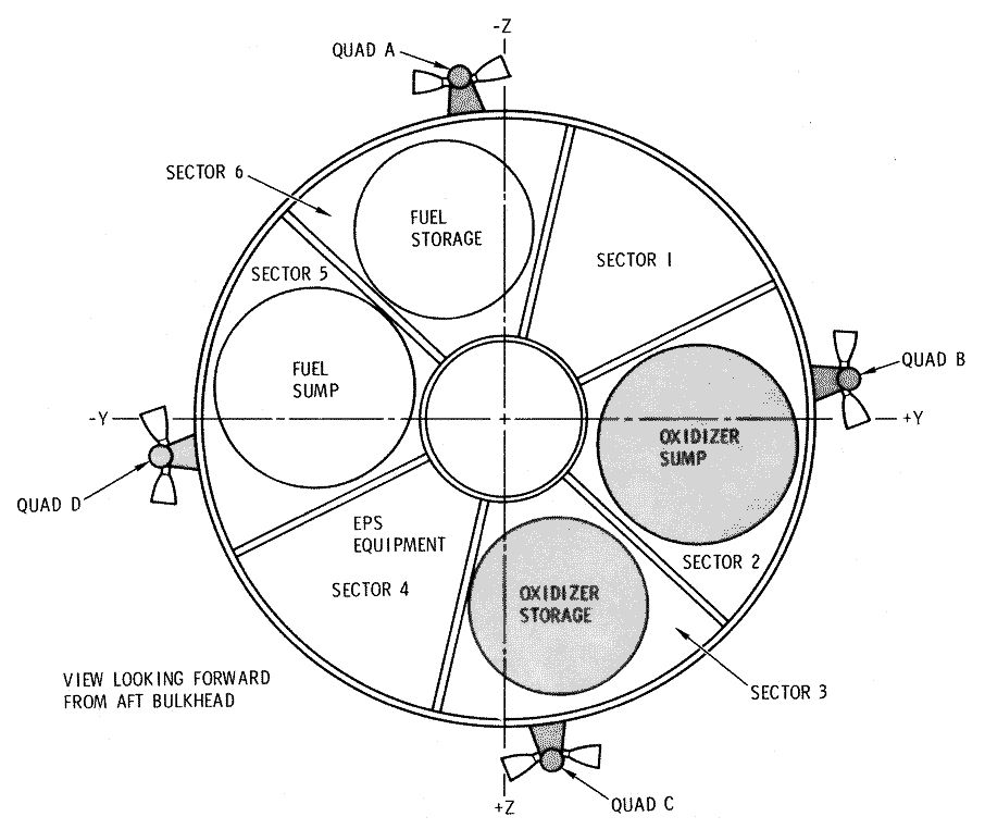
This quantity of SPS propellants totaled less than 10% of the SPS propellant capacity of the Block II Apollo CSM. A pair of new, shorter SPS propellant tanks in sectors 2 and 5, measuring 1.3 meters (4.25 feet) in diameter by just 22.9 centimeters (9 inches) tall, would, Hough calculated, suffice to contain this quantity of propellants. That would free up most of sectors 2, 3, 5, and 6 and the central cylindrical compartment for fuel cell reactants and other consumables. 

Block II Apollo CSM sector layout. Image credit: NASA.

The small amount of orbit maintenance propulsion required to avoid orbital decay during a long mission would, Hough wrote, be provided by the four Reaction Control System (RCS) thruster quads spaced evenly around exterior of the SM. The RCS would expend an average of about nine kilograms (20 pounds) of hydrazine fuel and nitrogen tetroxide oxidizer per day to maintain the CSML's orbital altitude and control its attitude, bringing the total RCS propellant load to about 846 kilograms (1880 pounds) for a 94-day CSML and about 1125 kilograms (2500 pounds) for a 125-day CSML. This would require expansion of the RCS tanks.

Hough proposed that four advanced "asbestos-membrane" fuel cells replace the three "Bacon-cell" fuel cells housed in sector 4 of the Block II Apollo SM. The latter were rated to operate for 400 hours (16.7 days), which was ample time to complete an Apollo lunar mission. He reported that a test version of the asbestos-membrane fuel cell had operated continuously for 1200 hours (50 days) and that it was expected to be capable of operating for up to 2500 hours (104.2 days). 

Asbestos-membrane fuel cells featured a handy in-flight start capability, Hough explained, permitting them to be operated in shifts to extend CSML orbital lifetime and increase redundancy. He envisioned that one or two would remain on "cold standby" at any one time. He calculated that two could produce three kilowatts of electricity continuously if they consumed an average of 1.23 kilograms (2.72 pounds) of liquid hydrogen/liquid oxygen reactants per hour. Three kilowatts was approximately double the amount of electricity needed for routine CSML "housekeeping" functions, thus making available about 1.5 kilowatts for DESM experiments. 

It is fair to ask why Hough did not consider systems other than fuel cells for generating CSML electricity. The Bellcomm engineer might have proposed that the CSML rely on solar arrays or an isotopic system, either of which would be less massive than fuel cells and heavily insulated tanks of cryogenic reactants. He explained that neither solar arrays nor a nuclear system had not been studied for use in XCSM missions, so they could not be considered to be within the bounds of Apollo technology as he defined them in his study. 

Hough acknowledged that, in spite of careful tradeoffs, his year-long mission tended toward tight consumables margins. For example, he allotted just three days of overlap for each resupply mission. This meant that "a few days of hurricane watch at KSC at the time of a resupply launch would cause termination of the total mission."

Though he studied it carefully, Hough was not especially enthusiastic about the CSML/DESM approach to a one-year mission. He explained that "it is probable that the CSML/DESM is not the best approach when compared to the self-sufficient new module" approach, though he maintained that "it appears to be optimum if the constraint of use of Apollo technology. . .is imposed." 

Hough argued that the main reason to settle for the CSML/DESM approach — aside from "a possible lean year or two of spacecraft launches" caused by AAP funding cuts — would be the appearance of new information concerning "man's compatibility with long-term spaceflight" that made the viability of long astronaut stays on board a self-sufficient module seem doubtful. In that case, attempting a one-year CSML/DESM mission to gain additional data ahead of a large investment in a new module might be seen as frugal.

He added that, if sufficient resources existed for both a one-year CSML/DESM mission and development of a self-sufficient module, then the CSML/DESM mission could be seen as a prudent step forward even if the viability of long-duration spaceflight were assured. Experiments in the DESM might include a prototype advanced power source independent of the CSML's fuel cells or test versions of long-duration life support systems. 

In August 1966, NASA took a step toward a "self-sufficient new module" when it opted to focus its Earth-orbital AAP efforts on the SSESM/spent S-IVB stage laboratory option. The space agency renamed the SSESM the Airlock Module; the spent S-IVB stage became known as the Workshop. In the Airlock Module/Workshop scenario, the CSM would serve mainly as a crew transport; the Airlock Module/Workshop would include independent life support and electricity-generating systems.

Apollo 9 CSM Gumdrop in low-Earth orbit as viewed from the LM Spider, March 1969. Image credit: NASA.

Sources

"Gemini 9 Underscores Knowledge Gaps," Aviation Week & Space Technology, 11 July 1966, p. 37.

"CSM Configuration Study for One Year Mission to be Achieved by Rendezvous and Resupply," W. W. Hough, Bellcomm, Inc., 21 July 1966.

"Washington Roundup — Apollo Roller Coaster," Aviation Week & Space Technology, 1 August 1966, p. 15.

"NASA Post-Apollo Plan Urged by Dec. 1," George C. Wilson, Aviation Week & Space Technology, 8 August 1966. pp. 26.

Skylab: A Chronology, NASA SP-4011, Roland W. Newkirk and Ivan D. Irtel with Courtney G. Brooks, NASA Scientific and Technical Information Office, 1977, p. 88.

More Information

Apollo Extension System Flight Mission Assignment Plan (1965)

Apollo Applications Program: Lunar Module Relay Experiment Laboratory (1966)

"Without Hiatus": The Apollo Applications Program in June 1966

Integral Launch and Reentry Vehicle: Triamese (1968-1969)

Triamese target: a large Earth-orbital "Space Base" assembled from modules launched atop two-stage Saturn V rockets. The Space Base, expected to be operational by about 1980, would be staffed by up to 100 people. Image credit: NASA.
The Triamese concept originated in 1967 in a reusable launch and reentry vehicle study General Dynamics Convair (GDC) performed on contract to the U.S. Air Force (USAF). Triamese owed its peculiar name to its peculiar launch configuration. At liftoff it would comprise one orbiter element and two booster elements. The boosters would together serve as the first stage; they would also provide propellants to the orbiter's engines during first-stage boost. One booster would attach to the orbiter's flat belly and the other to its rounded back. 

Space launch vehicle concepts with separate reusable booster and orbiter elements were not exactly new in 1967. What was different about Triamese was its strict reliance on a common booster and orbiter design. The Triamese orbiter and booster elements were intended to be virtually identical. GDC explained that

[i]n order to achieve the economy predicted for the Triamese system, the orbital and boost elements must have a high degree of commonality and must represent essentially a single development program. . .This commonality has been obtained by "overdesigning" the boost elements. . .[which] creates performance penalties that are accepted.

GDC called Triamese "a new mixture of aircraft, spacecraft, and launch vehicle." The Initial Point Design (IPD) Triamese launch stack (A, above) would have comprised two booster elements and one orbiter element, all virtually identical. It would have measured 149.5 feet (45.6 meters) tall from the trailing tips of its six rudder fins (two per element) to its three noses. B, a tail-on view of one element, shows the V-shaped, 46.1-foot (14-meter) spread of the rudder fins, 21-foot-wide (6.4-meter-wide) flat belly, and twin XLR-129 rocket engines arranged one above the other. Turning view B 45° horizontally yields view C. The IPD Triamese element would measure 31.4 feet (9.6 meters) from its belly to the tops of its rudder fins. View D displays "switchblade" wings deployed for stable subsonic flight. Wingspan is 107.5 feet (32.8 meters). Image credit: General Dynamics Convair/DSFPortree
The Triamese concept helped to shape NASA's May 1968 Integral Launch and Reentry Vehicle (ILRV) study Statement of Work and the ILRV Request for Proposal the space agency released to U.S. industry in October 1968. When time came for NASA to select four industry proposals for ILRV study contracts in January 1969, it was a foregone conclusion that Triamese would be counted among them.

NASA Marshall Space Flight Center (MSFC) in Huntsville, Alabama, was tasked with managing the GDC ILRV study contract. NASA MSFC was home of the three-stage Apollo Saturn V rocket. At the time of the ILRV study, Apollo Saturn V development, manufacture, and testing were drawing to a close. Managers at the Huntsville center hoped, however, that a two-stage Saturn V variant designated INT-21 might launch a series of increasingly complex space stations in the 1970s.

INT-21 consisted of the first two stages of the Saturn V — the S-IC first stage and S-II second stage — both of which measured 33 feet (10 meters) in diameter. An Earth-orbital payload measuring up to that diameter — for example, a large space station module — would replace the 21.7-foot-diameter (6.6-meter-diameter) S-IVB third stage of the Apollo Saturn V. 

One station program scenario, favored by NASA Administrator Thomas Paine, would see INT-21-launched Apollo Applications Program (AAP) Orbital Workshops — converted S-IVB stages — lead in 1975 to a large drum-shaped station with up to 12 crewmembers. Multiple INT-21-launched large station modules might then be joined together in orbit as early as 1980 to form a "Space Base" with up to 100 staff.

In that scenario, the ILRV shuttle would serve as a Saturn V supplement. The big rocket would do the heavy lifting all through the 1970s, leaving to the smaller reusable shuttle the specialized task of affordably launching astronauts, supplies, replacement parts, and scientific experiment apparatus to the space station and returning astronauts, experiment results, and data products to Earth. 

GDC began its ILRV Triamese study with an Initial Point Design (IPD) based on its USAF study results and inputs from NASA engineers. The IPD Triamese was designed to deliver up to 25,000 pounds (11,340 kilograms) of supplies and equipment to the space station and return up to 2500 pounds (1130 kilograms) to Earth during a single flight. The two boosters and the orbiter would each carry a flight crew of two astronauts, for a total of six. In addition, the orbiter would include a passenger compartment for transporting 10 astronauts to and from the space station. 

Orbiter and booster commonality was not the only cost-saving principle underpinning the IPD Triamese system. Another was use of off-the-shelf technology. GDC proposed, for example, that the design of the Triamese "switchblade" wings, which would enable stable flight at subsonic speeds, should be based on the variable-geometry wing system of the F-111 "Aardvark" aircraft the company manufactured for the USAF. 

The variable-geometry wings of the supersonic F-111 in action. In 1967, the F-111 became the first variable-geometry aircraft to enter active service. Image credit: U.S. Air Force.
GDC envisioned that the IPD Triamese elements would, like operational airplanes, fly repeatedly with minimal refurbishment between flights. The company acknowledged, however, that the elements would be subjected to greater stress during flight than would most aircraft, leading to greater potential for component failure.

GDC proposed to solve this problem by equipping IPD Triamese subsystems with sensors linked to on-board magnetic-tape flight recorders. After landing, data on subsystem performance would be carefully analyzed. Hardware that showed signs of actual or impending trouble would be subjected to detailed inspection and possible repair or replacement. 

The sensors would also enable a detailed on-board checkout capability that would slash costs by allowing NASA to get by with only a simple launch control center. KSC's Apollo Saturn launch control center was expansive and expensive, with many control consoles and an army of highly trained personnel; IPD Triamese launch control might more closely resemble an airport control tower. 

GDC expected that the IPD Triamese design, development, and test program would begin on 1 November 1971 and last until the first operational IPD Triamese flight on 1 January 1977, a period of 62 months. Engineering design would occur between 1 November 1971 and 1 July 1974. Development of the Pratt & Whitney XLR-129 rocket engine, which GDC called a "pacing item," would last from 1 November 1971 to 1 August 1974. Rocket engine tests using IPD Triamese vehicles that were captive  — that is, bolted down so that they could not take off — would take place between 1 March 1975 and 1 March 1976.

GDC proposed a "fatigue test vehicle" to help to ensure that the IPD Triamese elements would be as reusable as expected. This would take the form of a skeletal IPD Triamese element with all systems installed except for the metal plates and insulation blankets of its heat shield. 

Beginning on 1 November 1974, the fatigue test vehicle would undergo repeated propellant tank and cabin pressurizations, switchblade wing, turbofan jet engine, and landing gear deployments, computer starts, and other subsystem activations so that engineers could gain insight into malfunction characteristics and operational lifetimes. The tests would continue into the period of operational IPD Triamese flights.

The Initial Point Design (IPD) Triamese orbiter element differed from the booster element only in detail. Unless otherwise noted, all features called out in the side view drawing above are features of both the orbiter and the booster. A: cockpit for two astronauts seated side by side; B: passenger compartment for 10 Space Station crewmembers with seating arranged in three rows (orbiter only); C: forward landing gear (stowed). D: forward landing gear (down and locked); E: short liquid oxygen tank (orbiter); F: leeward forward pin connection (orbiter only); G: windward forward pin connection; H: cargo bay hatch (orbiter only); I: cargo bay (orbiter only); J: main landing gear (stowed); K: main landing gear (down and locked); L: short liquid hydrogen tank (orbiter only); M: switchblade wing compartment; N: leeward propellant feeds; O: windward propellant feeds; P: XLR-129 rocket engine (one of a pair); Q: body flap with elevons; R: rudder fin (one of a pair); S: rudder flap (one of a pair); T: extendible engine skirt (orbiter only — retracted); U: extendible engine skirt (orbiter only — extended). Image credit: General Dynamics Convair/DSFPortree.

Top view of IPD Triamese element. Unless otherwise noted, all features called out in the top view drawing above are features of both the orbiter and the booster. 1: cockpit windows; 2: cockpit crew hatch; 3: passenger compartment crew hatch/docking unit (orbiter only); 4: turbofan jet engine (stowed); 5: turbofan jet engine (deployed and locked); 6: long liquid oxygen tank (booster only); 7: reinforcing ring for attachment of forward pin connection (booster only) or connections (orbiter only), landing gear, and switchblade wing pivot; 8: switchblade wing pivot (one of a pair); 9: switchblade wing (deployed — one of a pair); 10: switchblade wing flap (one of a pair); 11: switchblade wing (stowed — one of a pair); 12: main landing gear (stowed); 13: cargo bay hatch/docking unit (orbiter only); 14: long liquid hydrogen tank (booster only); 15: aft attachment pin actuator (booster only); 16: leeward propellant feeds (one of a pair); 17: rudder fin (one of a pair); 18: rudder flap (one of a pair); 19: non-extendible XLR-129 rocket engine skirt (booster only); 20: body flap with elevons. Image credit: General Dynamics Convair/DSFPortree.

IPD Triamese flight testing would use "an aircraft approach." All flights would carry two test pilots per element — there would be no unpiloted IPD Triamese test flights. GDC allotted three booster elements and three orbiter elements for the IPD Triamese test program. Of these, two boosters and one orbiter would be carried over to operational flights. 

GDC scheduled 50 horizontal test flights at Edwards Air Force Base, California, between 1 October 1974 and 1 March 1976. During these tests, individual IPD Triamese elements would use their twin TF-34 turbofan jet engines to take off from a runway with their switchblade wings extended to verify subsonic flight and landing characteristics. 

The General Electric-built TF-34 engine generated 12,600 pounds (5715 kilograms) of thrust. GDC was familiar with the engine because it used it in its proposal for the U.S. Navy's S-3 Viking aircraft. The engine produced a characteristic low rumble, a sound that would no doubt have become associated with piloted spaceflight had NASA given GDC the nod to build the IPD Triamese.

A U.S. Navy S-3 Viking aircraft descends to a carrier landing. Visible is one of its two General Electric-built TF-34 jet engines. The IPD Triamese shuttle orbiter and booster elements would each have included two such engines. In the unlikely event that a returning IPD Triamese element missed its first attempt at a landing on the runway at NASA Kennedy Space Center, the jet engines would have permitted a second try. Image credit: U.S. Navy.
The company scheduled 15 single-element rocket-propelled vertical flights at NASA Kennedy Space Center (KSC) on Florida's east coast between 1 September 1975 and 1 November 1976. The tests would, among other things, enable verification of IPD Triamese flight characteristics at transonic and supersonic speeds. 

The IPD Triamese element under test would lift off from one of two launch pads built at KSC specifically for IPD Triamese launches, climb to a specified altitude, and shut down its twin rocket engines. It would then pitch over to horizontal attitude, deploy its wings and jet engines, and fly to a runway at KSC built specifically for IPD Triamese landings. 

In December 1975, the flight test program would shift into high gear as preparations began for suborbital two-element test flights, the first IPD Triamese flights to launch astronauts into space. A pair of joined booster elements would lift off vertically from a KSC IPD Triamese pad on 15 February 1976, separate, and undergo a reentry virtually identical to that they would experience during operational Triamese flights. They would then land on the KSC IPD Triamese runway. NASA would repeat this test on 1 April 1976. 

About two weeks later, on 15 April 1976, the first booster-orbiter suborbital flight test would take place. It would closely resemble the booster-booster tests. The second booster-orbiter test would occur on 1 June 1976. 

The IPD Triamese flight test series would end with a pair of three-element orbital flight tests on 1 August and 1 November 1976. The missions would see the first IPD Triamese dockings with an Earth-orbiting space station. 

The boosters and orbiter flown during the second orbital test flight would be used for "refurbishment verification" — a rehearsal of the normal IPD Triamese post-flight checkout and maintenance "turnaround" process — then the orbiter and one booster would be held in reserve as "standby elements" for the first operational flight of the IPD Triamese program on 1 January 1977.

Availability of standby elements — a backup orbiter and a backup booster — would be a standard part of preparation for every operational IPD Triamese mission. If an active orbiter or active booster suffered damage or malfunctioned and required time-consuming repairs, a standby element would fill in for it so that launch could go ahead as scheduled. This approach recognized the critical role reliable space transportation would play in NASA's space station program. 

GDC proposed that, in addition to the two standby elements, NASA's IPD Triamese fleet should include four active orbiters and six active boosters. The orbiters would each fly once per month, for a total of 48 orbiter flights per year. The boosters would each fly 16 times per year, for a total of 96 booster flights. 

Diagram of IPD Triamese orbiter and booster turnaround flow. In one month, four active orbiters would lift off from Kennedy Space Center, Florida. In the same period, four active boosters would fly once and two would fly twice. A fifth orbiter and a seventh booster would serve as "standby elements" ready to enter the turnaround flow if an active orbiter or booster should be grounded for repairs. Image credit: General Dynamics Convair/DSFPortree.

At the start of every operational IPD Triamese mission, turnaround technicians would load the 17.5-foot-diameter (5.3-meter-diameter), 12.4-foot-long (3.8-meter-long) payload bay located between the orbiter's liquid oxygen tank and its liquid hydrogen tank with 25,000 pounds (11,340 kilograms) of supplies and equipment bound for the Space Station. The orbiter propellant tanks would be made shorter than the booster tanks to make room for the 3000-cubic-foot (85-cubic-meter) bay.

Turnaround technicians would next pump consumables into the IPD Triamese elements. These would include 4660 pounds (2110 kilograms) of jet fuel for each booster and 1610 pounds (730 kilograms) for the orbiter, along with 3820 pounds (1730 kilograms) of attitude control propellants for the orbiter and 1420 pounds (645 kilograms) for each booster. 

The three elements would then be towed to the launch pad on their extended tricycle landing gear, hoisted vertical, and, after their landing gear was retracted, mounted on the pad on three support struts each. After the vehicles were joined to each other by three "pin connections," one forward and two aft, five support struts (the three supporting the orbiter and one each supporting the boosters) would be removed, leaving in place two per booster. 

Launch pad technicians would connect propellant feed lines linking the orbiter and the booster propulsion systems and attach umbilical hoses for propellant tank loading. After a leak check using on-board checkout equipment, they would fill the orbiter's tanks with 362,800 pounds (164,560 kilograms) of liquid oxygen and 51,830 pounds (23,510 kilograms) of liquid hydrogen. Each booster would be loaded with 424,500 pounds (192,550 kilograms) of liquid oxygen and 62,890 pounds (28,525 kilograms) of liquid hydrogen. Before vacating the vehicles, the pad technicians would conduct a final check of the propulsion system using on-board checkout equipment. 

The three flight crews and passengers would board, then the flight crews would perform a final check of all on-board systems save propulsion. Finally, at a time selected to enable a quick rendezvous with the Space Station, the six XLR-129 engines would ignite and power up to 20% of maximum sea-level thrust. There they would briefly hold to allow the flight crews to check engine performance. If all six engines were found to be operating normally, they would power up to 100%, hold-down attachments on the four support struts would disconnect, and the IPD Triamese stack would lift off.

IPD Triamese launch and ascent: the IPD Triamese launch stack (A) would stage at an altitude of 160,000 feet (48,770 meters) (B). The twin boosters would undergo a low-stress suborbital reentry (C), then would level off at 15,000 feet (4570 meters). Their flight crews would extend their jet engines and wings, then fly back in tandem to their NASA KSC base (D), a distance of 185 nautical miles (340 kilometers). The orbiter, meanwhile, would continue its journey (E) to the Space Station in 270 nautical-mile (500-kilometer) low-Earth orbit. Image credit: General Dynamics Convair/DSFPortree.

At liftoff, the four booster engines would each generate 394,500 pounds (178,715 kilograms) of thrust; the two orbiter engines, 380,000 pounds (172,365 kilograms) each. GDC calculated that the IPD Triamese stack would weigh 1,751,000 pounds (794,240 kilograms) at liftoff. Of this, the boosters would each account for 596,450 pounds (270,545 kilograms) and the orbiter, 558,100 pounds (253,150 kilograms).

During the first stage of ascent, the twin booster elements would supply all propellants to their own engines and the two orbiter engines. GDC did not specify how long first-stage flight would last. The company calculated, however, that the entire journey from launch pad to orbit would last only 6.2 minutes. Acceleration during ascent would top out at four times the pull of Earth's gravity.

GDC assumed that NASA's space station destination would circle the Earth in an orbit inclined 55° relative to Earth's equator. IPD Triamese launch azimuth would, however, be set at 35° to avoid overflight of the U.S. east coast early in the ascent phase. This meant that the orbiter would have to perform a westward yaw ("dogleg") maneuver to reach 55° orbit.

GDC estimated that flight conditions during ascent were 500 times more likely to cause a system failure than were conditions in space. As might be expected, engines, propellant feeds, and avionics were the systems most likely to malfunction. The company cited possible failure modes virtually certain to lead to structural failure and loss of life in as little as one second — for example, a hydraulic system failure that would cause the engines of one of the three elements to gimbal (pivot) and lock suddenly. 

To avoid such catastrophic failures, GDC proposed automatic malfunction detection and switchover to backup systems. This approach would, the company estimated, reduce the IPD Triamese catastrophic failure rate to one in 2000 flights.

Switching to backups might allow an IPD Triamese mission to proceed as normal. Even if an abort were necessary, under most circumstances the boosters would return to the KSC runway as normal. The orbiter, on the other hand, might seek to return directly to KSC, reach a low orbit and return to KSC after circling the Earth once (the generally preferred option), bank eastward and land downrange on the North Atlantic island of Bermuda, or, in the worst-case scenario, ditch at sea or crash-land on the Arctic ice cap. 

Booster thrust per engine would increase to 433,300 pounds (196,540 kilograms) just before burnout. The orbiter engines, meanwhile, would each extend an expendable skirt just before staging, allowing an increase in thrust per engine to 460,500 pounds (208,880 kilograms). 

The boosters would expend their propellants as the IPD Triamese stack reached a speed of 6800 feet per second (2070 meters per second). After booster separation, thrust per orbiter engine would steadily decrease until it reached 310,000 pounds (140,620 kilograms) just before shutdown. 

After they separated from the orbiter, the boosters would perform a suborbital reentry and turn toward KSC. They would deploy their switchblade wings and jet engines and fly back to base at a speed of 225 miles (365 kilometers) per hour. 

Staging during ascent to orbit: the operations illustrated above would last no longer than nine seconds. The orbiter (A) is shown with twin XLR-129 engines firing and engine skirts extended. Pyrotechnic bolts would fire in the booster (B) forward pin connections, allowing aerodynamic drag and inertia to cause the boosters to tip away from the orbiter. C: aft pin connection actuators on the boosters would simultaneously extend to ensure adequate clearance between the booster body flaps and the orbiter engine bells. D: after the boosters tipped back to an angle of 20° relative to the orbiter center line, pyrotechnic bolts would fire to sever the two aft pin connections. E: the aft pin connection actuators on the boosters would retract. The boosters would then roll to turn their windward sides toward their direction of flight and begin return to NASA Kennedy Space Center. Image credit: General Dynamics Convair/DSFPortree.

GDC proposed an IPD Triamese Reaction Control System (RCS) with 24 nitrogen tetroxide/hydrazine thrusters, most of which would cluster near the nose and tail. Of the 24, half would generate 1420 pounds (644 kilograms) of thrust and half 1160 pounds. 

Eight of the former would serve as orbital maneuvering thrusters, with four facing forward and four aft. These would permit the orbiter flight crew to circularize their orbit at space station altitude and perform rendezvous and station-keeping with the station. The company noted that the eight orbital maneuvering thrusters could be omitted from the boosters if doing so would save money.

The IPD Triamese orbiter mission would last 25 hours. Of this, the orbiter would spend 17.3 hours attached to the space station, during which time it would rely on station electricity, attitude control, life support, and communications. 

Precisely how the orbiter would link up with the space station was not explained. The liquid oxygen tank would be located between the cargo bay and the passenger compartment, preventing movement between them; for this reason, each would require an exterior hatch. This implies the existence of two docking units, one for each hatch, or a station hangar surrounding both hatches that could be pressurized. Though drawings show the cargo bay hatch as round, GDC described it as square and five feet (1.7 meters) wide. 

The company also did not describe the method of cargo transfer. No doubt the transfer of 25,000 pounds (11,340 kilograms) of supplies and equipment to the space station would need to be carefully orchestrated if it was to be completed in 17.3 hours. In addition, 2500 pounds (1130 kilograms) of cargo would be loaded into the cargo bay and 10 passengers at the end of their space station tour-of-duty would board the orbiter for return to Earth.

Shortly after departing the space station, the flight crew would use the orbital maneuvering thrusters to perform a deorbit burn, then carefully orient the orbiter for reentry. It would enter the atmosphere moving at 25,912 feet (7900 meters) per second at an altitude of 400,000 feet (122,000 meters) and would slow to 20,000 feet (6100 meters) per second at an altitude of 200,000 feet (61,000 meters). At these speeds, the orbiter would compress the thin air in its path, causing severe aerodynamic heating.

GDC described the IPD Triamese Thermal Protection System (TPS) heat shield in greater detail than any other system. Mostly it would comprise overlapping metal "cover panels" backed by thermal insulation blankets. The company divided the TPS into windward (nose, belly, and leading edge) and leeward (everywhere else) sections.

The composition of the TPS cover panels and the composition and thickness of the insulation behind them would depend on many factors. These would include orbiter reentry angle, banking angle, potential for air cooling, location on the orbiter, and the existence of new development programs aimed at perfecting existing TPS materials or producing new ones. 

The majority of the panels would be mounted on posts attached to the propellant tanks, which were meant to serve as "primary structure." GDC modeled its tank design on that of the Saturn V S-II second stage, which it said was made up of "cylindrical integrated pressure tanks." These could carry structural loads while unpressurized except during launch and ascent. In areas where no propellant tanks were available — mainly over the cockpit and passenger compartment, the cargo bay, and the engine compartment — the panels would be mounted on posts attached to a "trapezoidal framework." 

For its IPD Triamese TPS calculations, the company assumed an entry angle no greater than 1°. This would yield skin temperatures ranging from 3950° Fahrenheit (F) (2180° Celsius — C) on the windward side of the orbiter nose to 700° F (370° C) on the leeward side of the fuselage 90 feet (27 meters) aft of the nose. 

Most of the IPD Triamese would be covered by TD Nickel-Chromium (TD Ni-Cr) panels capable of withstanding a reentry temperature of up to 2400° F (1315° C). TD Ni-Cr is a thorium oxide-coated alloy. The panels would measure just 0.01 inches (0.254 millimeters) thick. At that thickness, they would weigh 1.75 pounds (0.8 kilograms) per square foot (0.09 square meters). GDC estimated that the typical TD Ni-Cr panel could withstand 50 reentries before it would need to be replaced. 

The nose and rudder fin leading edges would create special TPS problems. GDC called a thorium oxide-coated tungsten nose cap a "representative" state-of-the-art system. This would, however, need to be replaced after every third flight, so the company called for accelerated development of new TPS materials. The rudder fin leading edges, which would be made of costly coated tantalum, would need to be replaced after every 10th flight. 

The insulation blankets behind the panels would comprise layers of Microquartz and Dynaflex, products of the Johns Manville Corporation. Microquartz, which would make up one-third of the thickness of the blanket when used with Dynaflex, would be made of silica microfibers. It could withstand temperatures up to 1600° F (870° C). Dynaflex, an aluminum oxide, silica, and chromium oxide microfiber material that could withstand temperatures up to 2800° F (1540° C), would make up the remaining two-thirds of the blanket thickness.

Insulation blanket thickness and composition would depend on location on the vehicle. It would, for example, consist of Microquartz and Dynaflex and measure 3.7 inches (9.4 centimeters) thick on the windward side of the cockpit/passenger compartment area. A layer of Microquartz alone just 0.8 inches (2 centimeters) thick would suffice on the leeward side beginning about 60 feet (18.3 meters) aft of the nose.

The orbiter would maneuver during hypersonic reentry using its rudder fin-mounted flaps and body flap-mounted elevons. Initial calculations showed that a 20° bank initiated at 400,000 feet (122,000 meters) would permit a landing up to 450 nautical miles (830 kilometers) off the orbital track while causing an average increase in surface temperature of only 40° F (23° C). More detailed calculations suggested a different approach: a 45° bank gradually reduced to 10° at 200,000 feet (61,000 meters), then gradually increased again to 45°.

GDC proposed that vehicle primary structure temperature be controlled through "detailed air injection" during flight. Vents in the fuselage would be opened during descent to admit air, then ducts would channel it to hot areas to keep the temperature below 200° F (93° C). The company calculated that failure to air-cool the IPD Triamese orbiter would allow heat to "soak" into the vehicle, driving primary structure temperature to a punishing 330° F (166° C) 50 minutes after landing.

Like the boosters during their return to KSC, the orbiter would slow to subsonic speed at an altitude of 15,000 feet (4570 meters). It would, however, reach that altitude nearer the KSC landing strip than would the boosters. The orbiter would then deploy its TF-34 jet engines and switchblade wings. Subsonic flight under jet power would last no more than 10 minutes. 

About 400 feet (120 meters) above the ground, the flight crew would lower the landing gear and perform a flare maneuver, raising the orbiter's nose so that its main landing gear would touch the runway first. The flight crew and passengers would feel a deceleration equal to two times Earth's gravity at touchdown. Landing would occur at a speed of 180 miles (290 kilometers) per hour; rollout would measure less than 10,000 feet (3050 meters) with switchblade wing flaps down and less than 13,000 feet (3960 meters) with flaps up.  Maximum landing weight was 135,300 pounds (61,370 kilograms).

Desk model of Triamese launch (left) and landing flare configurations. The landing flare configuration model displays switchblade wings (colored orange), one of two deployed TF-34 jet engines (colored silver), and tricycle landing gear. Image credit: National Air and Space Museum.

Immediately after landing, the orbiter would again enter the turnaround flow, joining the boosters with which it had launched a little more than a day before. GDC determined that, under normal circumstances, an IPD Triamese orbiter would require 810 person-hours of turnaround servicing, while a booster would need 490 person-hours. A normal orbiter turnaround could be completed in a week by two teams of 23 technicians working two eight-hour shifts. Flight data recorder analysis, mission planning, and payload preparation would need additional time. 

Occasional additional tasks would add to turnaround time. GDC envisioned a special engine inspection every six months and an annual three-day "calendar inspection," which would see technicians visually inspect the interior of the liquid oxygen and liquid hydrogen tanks along with all wiring and plumbing. Every two years, technicians would spend three weeks performing "progressive rework" maintenance, during which they would remove the entire TPS to allow a detailed inspection of all vehicle systems and system replacement and updating as necessary.

As the ILRV study continued into the Spring of 1969, NASA, often acting at the request of the USAF, imposed new requirements on its contractors. Most new requirements reflected an ongoing shift in reusable vehicle purpose away from low-cost space station resupply and crew rotation and toward general spaceflight cost savings. 

In April 1969, NASA asked the ILRV contractors to add a 15-foot-wide-by-60-foot-long (4.6-meter-wide-by-18.4-meter-long) payload bay to the orbiter component of their designs. The contractors were also directed to study designs that could place 50,000 pounds (22,680 kilograms) or 100,000 pounds (45,360 kilograms) of payload into low-Earth orbit. 

At about the same time, the space agency requested that they study orbiter missions independent of a station lasting up to 30 days. Such missions would, in effect, see the orbiter function as a short-term space station. This was an ill omen for NASA's ambitious space station aspirations. 

Adding a large payload bay and long-duration missions to the IPD Triamese orbiter undermined the cost-saving principle of boost element and orbiter element commonality. GDC sought to accommodate the new requirements within its Triamese proposal; for example, the company proposed clustering more than two booster elements around an expendable second stage attached to a large payload. By October 1969, however, it was clear that the Triamese concept's days were numbered. 

On 13 January 1970, NASA Administrator Paine announced that the Saturn V assembly line would be shut down permanently. AAP would, however, continue under the new name Skylab. The Apollo 20 Moon mission would be canceled so that its Saturn V could be stripped of its S-IVB third stage and put to work launching Skylab into Earth orbit. 

That same month, the ILRV study was redesignated Space Shuttle Phase A. On 28 January 1970, GDC teamed up with North American Rockwell (NAR) to compete jointly for a Space Shuttle Phase B contract, which they subsequently won. GDC applied its ILRV study experience to the design of a reusable Booster for an NAR reusable Orbiter.

Sources

"Togetherness," M. Getler, Aerospace Technology, 17 July 1967, p. 70.

"MOL Switch Forthcoming," Aerospace Technology, 1 January 1968, p. 3.

Memorandum, Douglas Lord, Deputy Director, Advanced Manned Missions Program, NASA Headquarters, to Maxime Faget, Manned Spacecraft Center, "Manned Spacecraft Center Revised FY 1967 Advanced Study Program," 10 April 1968.

"Pace of Post-Apollo Planning Rises," W. Normyle, Aviation Week & Space Technology, 3 February 1969, pp. 16.

"NASA Aims at 100-Man Station," W. Normyle, Aviation Week & Space Technology, 24 February 1969, pp. 16-17.

"Large Station May Emerge as 'Unwritten' U.S. Goal," W. Normyle, Aviation Week & Space Technology, 10 March 1969, pp. 103, 105, 109.

Triamese Reusable Launch Vehicle/Spacecraft Status Report II, Report No. GDC-DCB69-014, General Dynamics - Convair Division, 7 May 1969.

A Shuttle Chronology 1964-1973: Abstract Concepts to Letter Contracts, Volume I: Abstract Concepts to Engineering Data; Defining the Operational Potential of the Shuttle, Management Analysis Office, Administration Directorate, NASA Johnson Space Center, December 1988, pp. I-10 - I-15, I-81 - I-83, I-85, I-87 - I-95, I-101 - I-102, II-108 - II-110, II-138 - II-140, II-156, II-158 - II-159, II-166 - II-167, II-182 - II-184.

More Information

"Without Hiatus": The Apollo Applications Program in June 1966

X-15: Lessons for Reusable Winged Spaceflight (1966)

"A True Gateway": Robert Gilruth's June 1968 Space Station Presentation

Think Big: A 1970 Flight Schedule for NASA's 1969 Integrated Program Plan

McDonnell Douglas Phase B Space Station (1970)