Showing posts with label Moon. Show all posts

ROMBUS: Reusable Orbital Module - Booster & Utility Shuttle (1963)

Engineer Philip Bono described his conceptual ROMBUS launch vehicle as a crew-carrying system, though he did not describe the crewed spacecraft it would launch. The image above displays a ROMBUS vehicle on its launch platform with a typical conical payload shroud. Image credit: Douglas Aircraft Company via San Diego Air & Space Museum.

As the 1960s decade began, NASA Marshall Space Flight Center (MSFC) had big ambitions. The Huntsville, Alabama-based facility, which left the U.S. Army to join NASA on 1 July 1960, aspired to build ever-more-powerful launch vehicles for the new U.S. space program. The Saturn family of rockets would, it was hoped, lead to the giant Nova booster, which might launch the first lunar landing mission and, eventually, lunar base hardware and spacecraft for crewed voyages to the planets.

Following President John F. Kennedy's 25 May 1961 call for a U.S. astronaut on the Moon by 1970, however, NASA selected the Saturn V rocket as its Apollo lunar landing mission workhorse. Interest in Nova outside NASA MSFC dwindled. This was bad news for the Huntsville rocketeers; if no Saturn successor was in development as Apollo reached the Moon, they might find themselves celebrating the first lunar landing with layoffs and facility closures.

NASA MSFC's response was to try to shape the civilian space program's course beyond Apollo. In May 1962, it hired three companies to carry out the EMPIRE study, which looked at 1970s crewed Mars/Venus flyby missions launched on "post-Saturn" rockets (see "More Information" below). The following month, it awarded contracts to study post-Saturn rockets with capabilities similar to those planned for Nova. The post-Saturn contracts called for designs of launch vehicles that could boost up to 500 U.S. tons/454 metric tons of payload to 200-mile-high/325-kilometer-high low-Earth orbit.

One of the post-Saturn rocket study contractors was Douglas Aircraft Company of Santa Monica, California. Douglas was no stranger to large rockets; the company had won the NASA contract to build the S-IVB rocket stage, the third stage of the Saturn V and the second stage of the Saturn IB, the Saturn V's smaller cousin.

Philip Bono headed up the 18-member post-Saturn rocket study team at Douglas. In June 1963, when he reported results of the first year of the study at the American Institute of Aeronautics and Astronautics (AIAA) Summer Meeting in Los Angeles, he was Chief Advanced Projects Engineer for Future Space Systems in the company's Missile & Space Systems Division Advanced Launch Technology Team

I have spotlighted Bono's imaginative concepts on this blog before (see "More Information" below). In 1960, while he worked for Boeing, he described a Mars expedition built around a scaled-up version of the Dyna-Soar space plane the company was developing for the U.S. Air Force. The heavy-lift rocket he designed to launch his Mars ship included plug-nozzle engines, about which more in a moment. In 1962, after he moved to Douglas, he proposed ROOST, a single-stage-to-orbit reusable launch vehicle. 

In addition to a clear view of the ROMBUS plug-nozzle engine (the turbopump exhaust port at the center of the plug and the ring of combustion chamber segments at the plug's edge are plainly visible), this view of the ROMBUS vehicle contains one inaccuracy and one (solved) mystery. The four landing legs should not be extended while the eight yellow liquid hydrogen tanks and the conical payload shroud remain attached to the centerbody. The large nozzles shown to the left of liquid hydrogen tank 7 and to the right of liquid hydrogen tank 3 are not discussed in written sources used in this post; they are, however, labeled in a blurry illustration (not in this post) as two of four solid-propellant rocket motors for thrust augmentation. Image credit: Douglas Aircraft Company via San Diego Air & Space Museum.

Four views of the ROMBUS launch vehicle. Upper left: bottom of the vehicle. Lower left: top of the vehicle. The center and right views are self explanatory. Image credit: U.S. Patent Office. 

The post-Saturn rocket Bono described to the AIAA, which he named ROMBUS, combined the plug-nozzle engine of his Mars expedition rocket with ROOST's single-stage-to-orbit design and reusability. Of these features, the plug-nozzle engine most defined the ROMBUS design.

The plug-nozzle rocket engine is a form of aerospike rocket engine. As its name suggests, in the typical 1960s aerospike engine a trailing cone or "spike" replaced the bell-shaped nozzle of the conventional rocket engine. In effect, as its proponents liked to say, the aerospike engine turned the bell-nozzle engine inside out.

Rocket plume size is governed in large part by ambient atmospheric pressure, which in turn is governed by altitude. At launch from Earth's surface, air pressure surrounding the plume is at its greatest. The bell-nozzle plume at launch is typically smaller than the inside of its engine bell, leading to plume instability, which in turn leads to reduced engine thrust. The plume increases in size to fill the bell as the rocket gains altitude and ambient pressure decreases, reducing instability and increasing thrust; in other words, bell-nozzle engine thrust increases toward optimum with increasing altitude. If the width of the plume should expand beyond the lip of the bell, however, instability recurs, again reducing thrust.

The typical aerospike engine is more efficient than its bell-nozzle counterpart because it maintains optimal thrust at all altitudes. Its plume, produced by multiple small thrust chambers mounted in a ring-shaped slot at the outer edge of the spike base, close to where the engine joined the body of the rocket, was shaped on its inner side by the inverted cone or concave curve of the spike surface and on its outer side by ambient air pressure. The plume and thrust level thus remained largely stable regardless of the engine's altitude, a characteristic Bono called "altitude compensation." He noted that the plug-nozzle engine's constant thrust  regardless of altitude  made it well suited for use in a single-stage launch vehicle.

In a conventional bell-nozzle engine, the plume heats the engine bell, so fuel is pumped through tubes in its the walls as coolant to prevent them from melting. In an aerospike engine, the plume would heat the spike and the ring-shaped slot containing the combustion chambers, so fuel  liquid hydrogen in the designs Bono considered  would be pumped through tubes in the spike and slot walls to prevent them from melting.  

The plug-nozzle rocket engine design Bono selected for ROMBUS, based on a design developed at the Rocketdyne Division of North American Aviation as part of an advanced Saturn rocket engine program, replaced the spike with a blunt plug with curved concave sides. The plug was only about a fifth as long as the spike of an aerospike engine with the same engine diameter. A turbopump exhaust port at the center of the plug would produce a plume that would, in effect, stand in for the missing four-fifths of the spike.

In addition to making the plug-nozzle engine more compact, this approach would make it lighter and easier to cool than the typical aerospike engine. Weight saved could be applied to payload.

Further weight savings would accrue through differential-thrust steering. A rocket with a conventional bell-nozzle engine would steer by gimbaling (swiveling) the rocket engine. This would require that the engine be mounted on a complex and heavy armature including flexible plumbing. The plug-nozzle engine, by contrast, could steer its rocket by selectively decreasing thrust in its combustion chambers. For example, reducing thrust from combustion chambers on the plug-nozzle engine's left side would cause the rocket to turn left. In addition to saving weight, the simpler plug-nozzle steering method was expected to increase reliability.

Bono described a typical ROMBUS mission. It would begin at one of four specially designed launch complexes located north of the Saturn V launch pads at NASA's Launch Operations Center (LOC) on Cape Canaveral in Florida. (NASA LOC would be renamed Kennedy Space Center six months after Bono presented his paper, following the assassination of President John F. Kennedy.) 

The 14-million-pound/6,350,300-kilogram ROMBUS launch vehicle would ignite the 36 combustion chamber segments in its 80-foot-diameter/24.4-meter-diameter plug-nozzle engine and ramp up to full thrust. Each segment would produce 500,000 pounds/226,800 kilograms of thrust, for a total thrust at liftoff of 18 million pounds/8,164,700 kilograms.

High thrust level would make ROMBUS a very noisy launch vehicle. Extrapolating from noise levels generated during tests of the much smaller Saturn I rocket, the first of which lifted off in October 1961, Bono tentatively estimated that the four ROMBUS launch complexes would need to be built at least 2.15 miles/3.45 kilometers apart to avoid damaging each other through launch noise. Adverse weather conditions at launch  low clouds and winds  could, he cautioned, amplify and reflect sound, potentially causing damage up to 16.8 miles/27 kilometers from a ROMBUS launch complex. 

Engine noise could also damage the reusable ROMBUS rocket itself. Bono expected that repeated exposure to high noise levels during launch would subject its structure to "acoustic fatigue." He called this "one of the principal structural problems attendant with vehicles of this size and thrust level." 

Bono designed his ROMBUS launch complex with destructive noise in mind. Each would include twin parallel arch-supported causeways bearing three piers near their centers. Between them the piers would support a launch platform to which the ROMBUS vehicle would remain bolted until its plug-nozzle engine reached full thrust. The causeways would span a 500-foot-diameter/153-meter-diameter, 60-foot-deep/18.3-meter-deep parabolic bowl partly filled with water to form a pool about 250 feet/76.2 meters across and up to 30 feet/9.14 meters deep. 

At ignition, the bowl would scatter sound away from the ROMBUS launch vehicle centerline, reducing acoustic fatigue effects; the water, meanwhile, would be displaced by the plug-nozzle engine plume, forming an "irregular quasi-parabolic shape" that would muffle noise.

Aerial view of a ROMBUS vehicle on its launch complex. A U-shaped mobile platform crawler moves away to the upper right of the vehicle. High noise levels meant that no human could be permitted within 900 feet/275 meters of the vehicle during launch; that is, they would need to stay beyond the ring road and the structures visible at upper center and at left. Image credit: Douglas Aircraft Company via San Diego Air & Space Museum.

Bono did not say how tall the fully assembled ROMBUS vehicle would stand at launch. Drawings such as this, however, which show a facility of known size (the parabolic dish of the launch complex would be 500 feet/153 meters in diameter), indicate that it was a little less than 250 feet/75 meters tall. Image credit: U.S. Patent Office/DSFPortree.

After its engine passed a quick checkout, the ROMBUS vehicle would be released from its launch platform to begin an eastward climb over the Atlantic. Bono estimated that ROMBUS could reach orbit even if six combustion chamber segments failed during ascent. 

During ascent, the plug-nozzle engine would draw liquid oxygen oxidizer from a spherical tank within its "centerbody." Eight 118-foot-long-by-25-foot-diameter/36-meter-long-by-7.5-meter-diameter cylindrical tanks attached to the sides of the centerbody would provide liquid hydrogen fuel.

Tanks 1 through 4, attached in pairs to opposite sides of the rocket to ensure stability, would supply all fuel during the first 130 seconds of flight; then, nearly empty, they would detach and tumble. At an altitude of about 30,000 feet/9145 meters, they would deploy parachutes, then would descend to a splashdown 34.5 miles/55.5 kilometers downrange of the ROMBUS launch complexes. Gaseous hydrogen pressure within the titanium-sandwich-skinned tanks would help to ensure that they would be sturdy enough to withstand water impact.
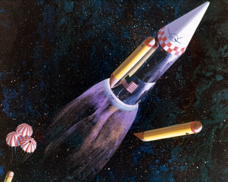
A ROMBUS vehicle during the final phase of its climb to orbit. Two liquid hydrogen tanks are shown immediately after separation; they are numbered incorrectly (they should be 5 and 6) and the tank at lower left has apparently experienced premature parachute deployment. The painting shows a small centerbody (with U.S. flag) and a disproportionately long cylindrical extension above it; both have reflective metal skin. Image credit: Douglas Aircraft Company via San Diego Air & Space Museum.

A NASA Landing Ship Dock retrieves the second of a pair of ROMBUS liquid hydrogen tanks. Also visible are the dome-shaped top of the first tank of the pair, the inside of the ship's well, one open well door, and two cranes. Image credit: Douglas Aircraft Company via San Diego Air & Space Museum.

Bono proposed that NASA acquire a surplus U.S. Navy Landing Ship Dock (LSD) for recovery of the floating tanks. LSDs were designed primarily to deploy landing ships bearing soldiers. Most of the space within an LSD's hull was taken up by a rectangular well that could be flooded. A pair of doors at the aft end of the ship opened the flooded well to the sea. Two cranes amidships, each capable of hoisting up to 50 U.S. tons/45.35 metric tons, could then be used to pull floating objects  such as ROMBUS liquid hydrogen tanks  into the well. 

After the well doors were closed, the water would be pumped out of the well so that objects taken in could be secured for transport using the cranes. Bono estimated that an LSD could retrieve and return to the LOC one pair of ROMBUS tanks at a time.

As ROMBUS ascent continued, two more opposing liquid hydrogen tanks would supply all fuel to the plug-nozzle engine, expend their contents, detach, tumble, and parachute to a splashdown 357 miles/575 kilometers downrange. The final opposing pair would separate at a low orbital altitude of 57.5 miles/92.5 kilometers and would, 19 minutes after separation from the ROMBUS centerbody, parachute into the Atlantic about 2760 miles/4440 kilometers downrange from the LOC. Bono estimated that tanks 5 through 8 would need additional thermal protection to withstand aerodynamic heating generated during their descent though Earth's atmosphere.

Bono provided no details of ROMBUS payload deployment or other orbital operations. Instead, he skipped to a novel reentry technique he believed the plug-nozzle engine would make possible. The technique would form a major element of the ROMBUS patent NASA was granted on his behalf in January 1967.

In its 200-mile-high/325-kilometer-high orbit, the centerbody would complete 16 orbits every 24 hours. The last of these orbits each day would carry it over an elliptical ROMBUS landing area centered between Orange City, Florida, and the Atlantic coast, about 30 miles/50 kilometers northwest of the ROMBUS launch complexes

Every 24 hours a radio command could thus be sent that would initiate centerbody return to the LOC. Upon receiving the command, the centerbody would face its plug-nozzle engine forward and briefly fire four combustion chamber segments spaced evenly around the combustion chamber slot. This maneuver would slow the centerbody by 500 feet per second/152 meters per second. With its plug-nozzle engine still facing forward, it would then begin its descent to the landing area.

Cutaway of the ROMBUS launch vehicle centerbody. Features are identified in the black and white illustration immediately below. Image credit: Douglas Aircraft Company via San Diego Air & Space Museum. 
The ROMBUS vehicle centerbody with important features labeled. Features are shown more clearly in the color image immediately above. Image credit: Douglas Aircraft Company via San Diego Air & Space Museum. 

Bono proposed that the forward-facing ROMBUS plug-nozzle engine could serve double-duty as a reusable active heat shield for protecting the centerbody from reentry heating. He believed that the system that cooled the plug-nozzle engine during ascent  liquid hydrogen flowing through tubes within the plug  could also keep the engine cool during reentry. Liquid hydrogen for the deorbit burn and reentry cooling would be carried in a spherical tank within the plug-nozzle engine. He suggested that, after cooling the plug, the hydrogen could be expelled through the plug-nozzle engine combustion chambers and turbopump nozzle, protecting them from reentry heating and further cooling the outside of the plug. 

In his 1963 paper Bono provided few details of his novel reentry method. In a 1976 book Bono co-authored with spaceflight writer Kenneth Gatland, however, he explained that plug-nozzle engine cooling would activate in "low-flow" mode as the centerbody descended below 400,000 feet/122,000 meters about 11 minutes before planned landing. After three minutes, as reentry heating neared its peak, cooling would switch to "high-flow" mode for four minutes. Then, four minutes before landing, the supply of cooling hydrogen would run out. 

A drogue parachute would deploy from the top of the centerbody to decelerate it below supersonic speed and enhance its stability. At an altitude of 30,000 feet/9145 meters, the drogue would detach and four or five main recovery parachutes would deploy. 

As the centerbody fell below 2500 feet/760 meters, the parachutes would detach and four combustion chambers would ignite. These would further slow descent and and steer the centerbody toward a precise landing spot. Bono suggested that a human on the ground aided by ground-based radar might remotely pilot the centerbody in the final descent phase. 

The centerbody would extend four landing legs. At touchdown, leg compression would trigger engine shutdown. At engine stop, the centerbody would weigh 500,000 pounds (227,000 kilograms) and stand 95 feet/29 meters tall. 

The ROMBUS launch vehicle centerbody ignites four of its combustion chamber segments and discards its main recovery chutes. Parts of each of the two zones (inner and outer) of the elliptical ROMBUS landing area are visible below the centerbody. The barge port is in view on the coast to the left of the centerbody, along with the road connecting it to the inner landing area zone; in the background, to the right of centerbody, Cape Canaveral and some of its spaceflight facilities can be seen. Image credit: Douglas Aircraft Company via San Diego Air & Space Museum. 
The centerbody has landed and a mobile platform crawler approaches. After the crawler picks up the centerbody, the four landing legs on the latter will be retracted. Image credit: Douglas Aircraft Company via San Diego Air & Space Museum. 

The ROMBUS mission would not be ended, however, for post-flight refurbishment constituted a critical and complex phase of operations. A U-shaped mobile platform on treads would be used to collect the centerbody and carry it overland from the landing site to a port facility on the Florida coast. There it would roll onto a barge to begin a 20-mile/30-kilometer journey south along the Intercoastal Waterway to the LOC. 

At the LOC, the barge would enter a canal leading to a special ROMBUS assembly building located north of the Saturn V Vertical Assembly Building (VAB). At the time Bono presented his paper, the VAB did not yet exist; construction began on 3 August 1963, less than two months after the AIAA Los Angeles meeting. Upon arrival at the ROMBUS assembly building, the mobile platform would disembark from the barge and deliver the centerbody to a refurbishment bay.

Partial cutaway of the ROMBUS vehicle assembly building at the Launch Operations Center, Cape Canaveral, Florida. The assembly building includes three bays. In the one at left, a payload shroud is lowered onto a ROMBUS vehicle; at right, a ROMBUS vehicle has left the building on its way to one of the four ROMBUS launch complexes, the nearest of which is at least 2.15 miles/3.45 kilometers away. At upper right, a barge arrives at the canal carrying a centerbody; at upper left, a Landing Ship Dock delivers a pair of ROMBUS liquid hydrogen tanks. Image credit: Douglas Aircraft Company via San Diego Air & Space Museum. 

Bono estimated normal ROMBUS turnaround time  which he defined as the time separating two launches  at 76 days. During that period, the centerbody would be partially disassembled, refurbished, reassembled, fitted with eight liquid hydrogen fuel tanks, loaded with a payload, and fitted with a launch shroud. A mobile platform crawler would then carry the launch vehicle to a ROMBUS launch complex for final preparations and a new flight to orbit.

Bono devoted two pages of his 20-page Los Angeles paper to text and charts detailing ROMBUS costs. He sought to prove that ROMBUS could yield a "four-fold improvement over current vehicles in (a) payload capability and (b) direct operating costs." ("Current launch vehicles" referred mainly to the Saturn family rockets.) On the whole, however, his cost estimates are not convincing, in large part because he failed to define his cost estimation methodology. 

He wrote of an annual ROMBUS program cost of $1 billion a year, and a total program cost including facilities, operations, and development of between $9 billion and $17 billion. Of this total, development cost ranged from $5.1 billion to $8.6 billion. 

Cost per pound of payload to orbit varied considerably depending on which factors Bono chose to consider. For example, he estimated that a reliability of 0.85 would yield a cost of $12 per pound/$26 per kilogram; upping reliability to 0.95, as might be achieved as NASA gained experience over the course of the ROMBUS program, would reduce cost to $5 per pound/$11 per kilogram.

In his 1976 co-authored book, Bono arrived at a cost of $25 per pound/$55 per kilogram if the ROMBUS vehicle could be reused 20 times; 100 reuses would reduce cost to $10 per pound/$22 per kilogram "or less." These estimates may reflect methodologies NASA applied in the early 1970s to generate Space Shuttle cost estimates, which would turn out to be seriously flawed.

Bono suggested that ROMBUS might be flown economically with less than its maximum payload. It would then amount to a "reusable 'trucking' system" that could replace existing smaller expendable launch vehicles. Flights with reduced payloads would need less liquid hydrogen fuel and liquid oxygen oxidizer; this meant that they would need fewer liquid hydrogen tank pairs. He wrote that, for a mission that would see ROMBUS launch a nuclear-thermal rocket upper stage to an altitude of 106,000 feet (32,300 meters) for a suborbital reactor start, the liquid oxygen tank in the centerbody would need only be filled halfway. 

NASA MSFC pulled the plug on the Douglas post-Saturn launch vehicle study in March 1964. This did not, however, prevent Bono from continuing to propose vehicles that resembled ROMBUS. In his 1976 co-authored book, for example, he described Hyperion, a sled-launched 55-passenger orbital crew transport; Pegasus, a suborbital 172-passenger crew/cargo transport capable of traveling 7456 miles/12,000 kilometers in just 39 minutes; and the Ithacus intercontinental troop transport, which could carry 260 soldiers and their equipment anywhere in the world. All were, like ROMBUS, reusable single-stage vehicles with plug-nozzle engines.

In June 1964, NASA MSFC director Wernher von Braun acknowledged that post-Saturn launch vehicles had no future by calling publicly for future crewed planetary missions to use the Saturn V launch vehicle. By November of that year, President Lyndon Baines Johnson's White House made clear that the NASA space program after Apollo should emphasize Earth-orbital operations and rely on rockets and spacecraft developed for the Apollo lunar landing program.

Sources

"ROMBUS - An Integrated Systems Concept for a Reusable Orbital Module (Booster & Utility Shuttle)," Douglas Engineering Paper No. 1552/AIAA Preprint No. 63-271, P. Bono, Douglas Aircraft Company; paper presented at the First National Summer Meeting of the American Institute of Aeronautics and Astronautics, Los Angeles, California, 18 June 1963.

Design No. 201,773. Recoverable Single Stage Spacecraft Booster, "James E. Webb, Administrator of the National Aeronautics and Space Administration, with respect to an invention of Philip Bono," US Patent Office, 16 June 1964 (filed), 27 July 1965 (granted),

Patent No. 3,295,790. Recoverable Single Stage Spacecraft Booster, "James E. Webb, Administrator of the National Aeronautics and Space Administration, with respect to an invention of Philip Bono," US Patent Office, 16 June 1964 (filed), 3 January 1967 (granted).

Frontiers of Space (Revised Edition), P. Bono and K. Gatland, MacMillan Publishing Company, 1976, pp. 63, 66, 69-70, 163-168, 197-200, 218.

Stages to Saturn: A Technological History of the Apollo/Saturn Launch Vehicles, NASA SP-4206, R. Bilstein, NASA, 1980, pp. 37, 50-60.

San Diego Air & Space Museum Image Collection (https://sandiegoairandspace.org/collection/image-collection — accessed 6 May 2025). 

More Information

Dyna-Soar's Martian Cousin (1960)

Reusable One-stage Orbital Space Truck (ROOST) (1962)

EMPIRE Building: Ford Aeronutronic's 1962 Plan for Piloted Mars/Venus Flybys

X-15: Lessons for Reusable Winged Spaceflight (1966)

Nomad Explorer (1992)

The Nomad Explorer Very Long Traverse Vehicle (VLTV) with its "power cart" in the background (right). A cable links the cart's nuclear reactor to the VLTV. Please note the "periscope" viewing window (below Earth at upper left), robotic arm (one of a pair), and EVA Bell (lower center). Image credit: Madhu Thangavelu
North America and Europe combined have fewer square kilometers of surface area than the Moon: 36.8 million for the two continents versus 37.8 million for Earth's natural satellite. In August-September 1992, at the 43rd Congress of the International Astronautical Federation (IAF) in Washington, DC, Madhu Thangavelu, a research associate at the University of Southern California's Institute of Aerospace Systems Architecture and Technology, argued that explorers operating from a fixed surface base — the traditional advanced lunar exploration scenario — could hope to survey only a small fraction of the lunar surface. Moreover, only after several costly piloted lunar landing missions had investigated candidate sites could a single fixed base site be selected.

At the time Thangavelu presented his paper, the Space Exploration Initiative (SEI), launched by President George H. W. Bush on the 20th anniversary of the first piloted Moon landing (20 July 1989), was nearing its end. Though at SEI's start NASA had proposed a traditional fixed-site permanent lunar base concept, by the time of the 1992 IAF meeting it had shifted its attention to a temporary lunar outpost concept called First Lunar Outpost (FLO). NASA made the change based on recommendations in the May 1991 report of the SEI Synthesis Group (the Stafford Committee).

Thangavelu did not mention FLO in his paper, though he might have noted that it had many of the limitations of the fixed-site base scenario. In its most basic form, FLO would see a series of 45-day piloted lunar missions, each employing one Habitat Lander and one Crew Lander. FLO astronauts would have at their disposal roving vehicles not too different from the jeep-like Apollo rovers. These would permit traverses of at most a few tens of kilometers from their temporary lunar outpost.

Thangavelu suggested that NASA replace the fixed-site lunar base approach with a "roving base" that would, in a single ambitious piloted mission, explore multiple candidate base sites and the terrain between them along an 11,000-kilometer traverse route. He called his roving base Nomad Explorer. 

The chief element of the Nomad Explorer roving base was the 35-tonne Very Long Traverse Vehicle (VLTV), which would measure 16 meters long, 4.5 meters wide, and 10 meters high. The VLTV would roll on four large wheels, each powered independently by a 120-horsepower electric motor. The complex wheels would change shape automatically to accommodate obstacles and ensure a smooth ride. Typically, the VLTV would move at about 20 kilometers per hour, though it could trundle along at up to 30 kilometers per hour if necessary.

The VLTV would provide its three-person crew with 600 cubic meters of pressurized volume. It would include a control cockpit, crew quarters, a meeting room/galley, an airlock, and a hygiene facility. 

Life support water tanks and stacked bags containing lunar dirt on the vehicle's roof would partially shield against solar flare and galactic cosmic radiation. A periscope-like assemblage of mirrors and baffles would provide the driver with an elevated view of the surface while blocking some radiation; along with movable cameras and floodlights, it would augment a more conventional  "windshield" with sloping tinted windows directed toward the surface.

Thangavelu proposed a novel system for providing the Nomad Explorer roving base with electricity — an automated "power cart" bearing a nuclear reactor that would follow about a kilometer behind the VLTV to limit crew radiation exposure. It would supply 50 kilowatts of electricity to the piloted rover either through a long durable cable or through intermittent microwave beaming. An auxiliary fuel cell/solar cell system on the VLTV would provide 10 kilowatts of backup electricity.

The most novel feature of Thangavelu's Nomad Explorer design was, however, the EVA Bell, an accordion-like structure that would extend down from the VLTV's underside. Thangavelu intended that the 48-cubic-meter EVA Bell should eliminate what he considered to be the worst feature of moonwalks: the need for bulky space suits. Space suits, he explained, decreased astronaut mobility and dexterity, caused fatigue, and required excessive time for donning. The EVA Bell would also protect the astronauts from abrasive lunar dust.

In addition to the EVA Bell, the VLTV would include two robot arms that could stand in for or assist space-suited astronauts. These would ride on tracks on the VLTV's exterior, enabling them to reach out from the rover in any direction.

The Nomad Explorer roving base would, of course, require a supporting space transportation infrastructure. Thangavelu envisioned a revived Saturn V rocket which he called the "Saturn V-B." This would launch Autonomous Modular Common Landers (AMCLs) configured for either automated or piloted operation. Though he did not mention it, NASA's proposed FLO launch vehicle, informally dubbed the "Saturn VI," might have stood in for the Saturn V-B with modest uprating or if used in an Earth-Orbit Rendezvous architecture. Uprated, modified FLO Crew and Habitat Landers might have replaced the AMCLs.

An automated AMCL would land the Nomad Explorer roving base at the start of its planned traverse route. Others would land supplies and experiment payloads no more than 3000 kilometers apart along the route. A one-way piloted AMCL would deposit the VLTV crew near the roving base at the starting point of the long traverse, and an automated AMCL bearing a crew Earth-return vehicle would land at the end of the traverse route.

The astronauts would then begin their six-month journey across the Moon's rolling, dusty terrain. Upon reaching the first resupply AMCL, they would use the VLTV's robot arms to transfer supplies it carried to a special port on the VLTV, then would put the EVA Bell into action. First, they would use the VLTV's robot arms to spread a "mat" on the lunar surface. The crew would then use the arms to transfer a site-specific scientific payload from the AMCL to the center of the mat.

Next, the astronauts would position the VLTV so that it straddled the payload. They would extend the EVA Bell, which would lock onto the mat, forming an air-tight seal. The astronauts would fill the EVA Bell with air, then would climb down into it to deploy the payload. After they completed their tasks, they would exit the EVA Bell, pump out its air, and raise it off the mat, exposing the payload to lunar surface conditions.

In addition to scientific instruments, the astronauts would deploy a telecommunications network for future operations as they moved over the lunar surface. Upon reaching the end of their traverse, they would place the Nomad Explorer roving base in "hibernation." They would then board the pre-landed AMCL Earth-return vehicle and blast off for home.

Source

"The Nomad Explorer Assembly Assist Vehicle: An Architecture for Rapid Global Lunar Infrastructure Establishment," IAF-92-0743, Madhu Thangavelu; paper presented at the 43rd Congress of the International Astronautical Federation, 28 August-5 September 1992, Washington, DC.

More Information


The Proper Course for Lunar Exploration (1965)

Image credit: NASA.

For a time in the early 1960s, Thomas Evans headed up the Advanced Lunar Missions Study Program in the NASA Headquarters Office of Manned Space Flight. By May 1965, when the 11th Annual Meeting of the American Astronautical Society (AAS) was held in Chicago, Illinois, he had retired from NASA to become a farmer in Iowa. This gave him the freedom to speak his mind about what he felt were the Apollo Program's shortcomings.
 
Evans told assembled members of the AAS that "the idea of a manned [landing] on the [M]oon was so spectacular. . . that [it] dominated most pronouncements and thoughts on the space program." He then declared that the objective had "too much the flavor of a stunt to be the final goal of a $20 billion national effort." Evans argued that 
[Our] situation today is comparable to one which might have occurred during the railroad building era in America a century ago. It is as if the federal government had invested vast sums in the construction of the first railroad spanning the North American continent, but had procurred only a single engine and caboose. . . The first crossing by that engine and caboose would have been a major milestone in man's progress and would have been greeted with enthusiasm and applause. But then those responsible for the program would have faced a major decision. . . Should the project be stopped? Should the engine-caboose be run repeatedly back and forth across the Continent to constantly remind the world of our great achievement? Or should a further modest investment be made in. . . some freight and passenger cars, to convert the system into something of practical value? Only the last solution would have been tenable then, and only a similar constructive approach would seem acceptable now. 
Evans was hopeful that good sense would prevail. He pointed to statements by President Lyndon Baines Johnson and Vice-President Hubert Humphrey (chair of the National Space Council) which he said made clear that "the United States fully intends to explore the [M]oon, not merely to visit it." He explained that the Saturn rockets and Apollo spacecraft NASA had under development would provide "an excellent base upon which to build a broad program of manned. . . lunar exploration beyond the first landing."

He noted that NASA expected to be able to launch six Saturn V rockets per year beginning in 1969. After explaining that "most Saturn Vs will be used for lunar operations since there are only a limited number of credible missions for this vehicle in earth orbital and planetary programs during the early 1970s," Evans outlined four candidate Saturn-Apollo-based lunar exploration programs. 

In the first, the baseline Apollo program, a single Saturn V rocket would launch a Apollo Command and Service Module (CSM) carrying three astronauts and the Lunar Excursion Module (LEM) (as the Apollo Lunar Module — LM — was known at this time). Two astronauts would land on the Moon in the LEM for a one-day stay. They would explore an area 0.2 miles in radius centered on their LEM. The crew would have at its disposal only 250 pounds of payload such as scientific instruments. 

The baseline Apollo Lunar Excursion Module (LEM) on the Moon as envisioned in 1964. Image credit: Grumman/NASA.

Evans' second candidate program would be based on the Apollo Extension System (AES) that NASA had begun to study as early as 1963. This option would, he explained, permit "sophisticated orbital survey. . . to gather data on the entire surface of the [M]oon," as well as lunar surface stays lasting up to 14 days. 

Two Saturn V rockets would be required for each AES lunar surface mission. The first would launch a piloted CSM and an automated cargo LEM loaded with 2500 pounds of supplies and equipment. The CSM would transport the cargo LEM (often called a LEM Shelter) to lunar orbit, then the LEM would separate and land automatically on the Moon. The CSM and its crew would then return to Earth. 

The second Saturn V would launch three astronauts and Apollo CSM and LEM spacecraft "improved" to enable long missions. Two astronauts would land in the improved LEM near the cargo LEM, which would serve as their shelter during their 14-day surface stay. They would use a small surface rover or a pair of flying vehicles to explore an area five miles in radius. 

The third candidate program, based on Apollo Logistic Support System (ALSS) studies, would also use two Saturn Vs per 14-day surface expedition, but would differ from AES in that the LEM Truck, a beefed-up LEM descent stage capable of delivering four tons of payload to the lunar surface, would replace the cargo LEM. The LEM Truck's principal payload, Evans wrote, would be the Mobile Laboratory (MOLAB), a pressurized rover that would permit two astronauts to explore an area 50 miles in radius. 

The Northrup MOLAB pressurized lunar rover would have arrived on the Moon atop of modified LEM descent stage (LEM Truck). The cylinder on top of the tubby pressurized compartment is the docking unit for linking with the Apollo CSM that delivered the MOLAB/LEM Truck to lunar orbit. This was one of several pressurized rover designs put forward in the mid-1960s. Image credit: Northrup/NASA.

Evans noted that, in spite of their impressive capabilities, the AES and ALSS cargo delivery systems would be "inherently inefficient" because astronauts would need to travel to the Moon and back to deliver each automated cargo lander. This would mean that the mass of the CSM systems required for crew support and Earth-return (life support, lunar-orbit departure and course-correction propellants, reentry heat shield, and parachutes) would need to be subtracted from the mass of the payload that the AES and ALSS systems could deliver to the Moon's surface.

Lunar Exploration Systems for Apollo (LESA), the fourth program Evans described, would avoid this inefficiency. LESA, Evans explained, was "a family of shelters, vehicles, and other equipment. . . tailored to support not only short-term reconnaissance operations by two or three astronauts but also semi-permanent scientific stations manned by up to 12 or even 18 men." 

LESA 1 Shelter with rover. Image credit: Boeing/NASA.

The Saturn V-launched LESA Shelter lander would follow a direct-ascent trajectory from Earth to the Moon, so would need no CSM. This would enable delivery of up to 14 tons of payload. Crew delivery at first would be by improved Apollo CSM and an upgraded LEM capable of landing three men on the Moon. The CSM would remain in hibernation in lunar orbit while the crew was on the surface; the LEM would hibernate on the surface while its crew lived in the LESA Shelter.

A 90-day, three-man LESA 1 expedition would explore an area 80 miles in radius; a 365-day, 12-to-18-man LESA 3 outpost made up of additional Shelters and other specialized modules (for example, a nuclear power plant) and relying on advanced direct-ascent landers for crew rotation and resupply would survey an area 200 miles in radius. The former would require a total of three Saturn V launches; the latter, 10 to 17 Saturn V launches. 

Developing the AES would cost an additional $500 million over the $20 billion already committed to Apollo, Evans estimated, while ALSS development would cost $1 billion. Developing LESA 1 would cost $2 billion — just 10% of the amount already committed to Apollo. LESA 3 would evolve from LESA 1 for an additional $800 million.

Evans then proposed a two-phase post-Apollo lunar program. In Phase I, which would be based on AES, ALSS, or LESA 1, astronauts would explore three areas of the Moon judged to be of "major geoscientific interest" totaling up to 1800 square miles ("a meager sample," Evans noted, "of the total 10 million square miles of lunar surface"). In Phase II, which would be based on LESA 3 modified for six astronauts, NASA would maintain an outpost on the Moon for four years. 

Evans compared operations costs of the four programs. He determined that a combination of LESA 1 in Phase I and modified LESA 3 in Phase II would be most economical, with a total cost of less than $8 billion. ALSS/modified LESA 3, with an operations cost of $8.3 billion, would also be economically acceptable, while AES/modified LESA 3 would be "a disastrous selection" — together, the two phases would cost a total of about $20 billion. 

The retired NASA manager ended his paper by broadly assessing the state of NASA lunar planning. He noted that, of the $26 million allotted to planning for advanced piloted lunar systems in the Fiscal Year 1965 NASA budget, most was budgeted for examination of inefficient and limited systems such as AES. "Only a trickle," he wrote, was devoted to the study of "more sophisticated and efficient systems." 

NASA and its contractors continued studies of advanced lunar systems throughout the 1960s and into the early 1970s. Studies focused mainly on AES/ALSS-type missions. It was hoped these would fly during the 1970s as part of the Apollo Applications Program (AAP), which became AES's successor shortly after Evans' May 1965 presentation. At the same time, scientific advisory groups advocated for advanced lunar exploration.

Apollo did not, however, imply a long-term national commitment to lunar exploration. Between 1964 and 1968, President Lyndon Baines Johnson repeatedly signaled his support for an Apollo-derived post-Apollo NASA program; lack of support for the program in Congress, however, caused NASA Administrator James Webb to turn the agency's efforts increasingly away from post-Apollo lunar exploration. In addition, the Apollo 1 fire of 27 January 1967, which killed astronauts Gus Grissom, Ed White, and Roger Chaffee, did immeasurable damage to NASA's post-Apollo prospects.  

NASA Administrator James Webb (center) with Vice-President and National Space Council chair Hubert Humphrey (left) and President Lyndon Baines Johnson (right). Image credit: NASA.

In the 1969-1971 period, when NASA Administrator Thomas Paine's Integrated Program Plan (IPP) held sway, the space agency and its contractors studied complex and costly lunar transportation systems (such the Nuclear Shuttle), space stations in lunar orbit, and permanent lunar surface bases. Such plans received no support from the Administration of President Richard Nixon, however, and all IPP planning ceased soon after Paine's resignation in September 1970. 

Despite these setbacks, some features of AAP lunar advance planning found their way into the last three Apollo missions to the Moon (Apollos 15-17). Designated J-class, their technological improvements included heavier lunar surface payloads, enhanced lunar surface mobility, space suits with greater flexibility and endurance, longer lunar surface stay times (up to three days), added lunar surface scientific instruments, a bay full of Moon-pointing scientific sensors in the lunar-orbiting CSM, and a subsatellite ejected into lunar orbit from the CSM.

The image at the top of this post illustrates the course U.S. lunar exploration took after Evans presented his paper. It shows Apollo 17 Commander Eugene Cernan saluting Old Glory in the Taurus-Littrow valley in December 1972. 

Apollo 17 left Earth atop the penultimate Saturn V rocket to fly (the last to fly would launch the Skylab Orbital Workshop, the last vestige of AAP, into low-Earth orbit in May 1973, eight years after Evans' presentation). Apollo 17's jeep-like Lunar Roving Vehicle (just visible behind Cernan) ranged up to 7.6 kilometers from its home base, the LM Challenger (behind flag), during three traverses spanning three days. The only professional scientist to reach the Moon, geologist and Lunar Module Pilot Harrison Schmitt, snapped the picture. 

Source

"Lunar Exploration: What is the Proper Course?" Thomas Evans, Post Apollo Space Exploration, Francis Narin, editor, 1965, pp. 647-661; paper presented at the 11th Annual Meeting of the American Astronautical Society in Chicago, Illinois, May 3-6, 1965.

More Information


S-IVB/IU Applications: The LASS Proposal (1966)

Douglas Aircraft Company built the S-IVB stage and IBM built the Instrument Unit (IU) that rode atop it. In the image above, the S-IVB/IU combination for the Apollo 4 mission is hoisted in the Vertical Assembly Building at NASA Kennedy Space Center (KSC), Florida. The black ring at the top is the IU; the red object mostly hidden by the tapered interstage adapter at the bottom is the S-IVB's J-2 rocket engine bell in a red protective wrapping. The study described in this post drew to its conclusion as this, the first S-IVB/IU intended for flight, began pre-launch preparations at KSC. Apollo 4, the first flight test of the Saturn V, flew without a crew on 9 November 1967. The Apollo 4 S-IVB/IU performed flawlessly. Image credit: NASA.

Finding new roles for space hardware that exists or is under development is a common objective of spaceflight advance planners. They aim to accomplish new tasks in space while reducing development time and cost; if they work for a contractor and propose new roles for hardware that their company is on contract to produce, they might also hope to generate new contracts and new revenue. Advance planners employed by NASA may also seek to find new ways to exploit existing hardware; their objectives in doing so can often be complex. 

Many examples of proposals to repurpose space hardware can be cited. The reader may explore some of them by clicking on links in the "More Information" section at the bottom of this post. 

In this post we zero in on a proposal for repurposing two important elements of Apollo-era space hardware: the S-IVB rocket stage, which formed the second stage of the two-stage Saturn IB launch vehicle and the third stage of the three-stage Saturn V launcher, and the Instrument Unit (IU), the "electronic brain" of the Saturn IB and Saturn V, which rode into space bolted atop the S-IVB. The authors of this proposal were engineers at Douglas Aircraft Company, the prime contractor of the S-IVB, and International Business Machines (IBM), the prime contractor of the IU. 

Image credit: NASA.
Image credit: NASA.

The Douglas/IBM team performed its "Lunar Applications of a Spent S-IVB/IU Stage (LASS)" study using company funds between November 1965 and July 1966, shortly after the official start within NASA of the Apollo Applications Program (AAP) in August 1965. During AAP, the U.S. civilian space agency encouraged and invited proposals for new uses of hardware under development for the Apollo lunar program.

The S-IVB and IU were designed to reach Earth orbit during Apollo Earth-orbital missions and to leave Earth orbit with enough energy to fly past the Moon during Apollo lunar missions. This meant that, even without modifications, they would reach places in space where they might serve new useful purposes. As AAP gained steam in the 1965-1966 period, the S-IVB and IU thus became prime candidates for application to new missions throughout cislunar space and beyond.

The LASS proposal grew out of a 1964 plan to make use of the Saturn IB S-IVB stage in low-Earth orbit. The S-IVB, which included (from top to bottom) a large tank for liquid hydrogen (LH2) fuel, a smaller tank for liquid oxygen (LOX) oxidizer, and a single J-2 engine capable of generating about 200,000 pounds (890,000 newtons) of thrust, would typically reach Earth orbit with an Apollo Command and Service Module (CSM) spacecraft on top during Apollo Earth-orbital missions. The CSM would weigh about 40,000 pounds (18,145 kilograms).

The large enclosed volume of its tanks and the payload it could place into orbit made the S-IVB a natural candidate for exploitation as the basis for an Earth-orbital laboratory. In 1965-1966, the favored scheme was to launch a two-stage Saturn IB with a modified S-IVB second stage carrying a Spent-Stage Experiment Support Module (SSESM) in place of a CSM with a crew. At the time the Douglas/IBM team performed the LASS study, the first S-IVB/SSESM combination was scheduled to reach Earth orbit early in 1968 as part of the SA-209 AAP mission.

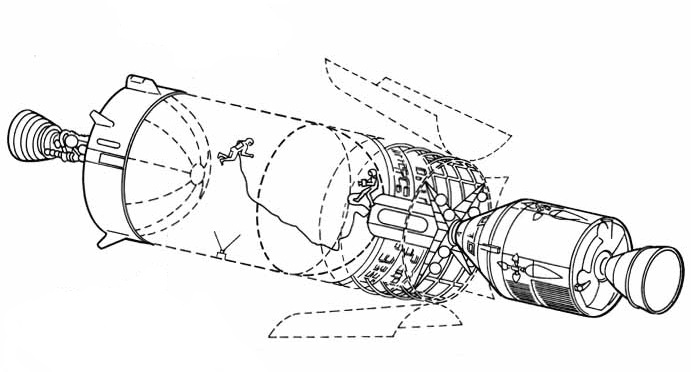
An S-IVB-derived Earth-orbital laboratory with an attached Spent-Stage Experiment Support Module (SSESM) and, at right, a docked, separately launched Apollo Command and Service Module (CSM). Image credit: NASA.

After reaching orbit, commands transmitted from the ground — or perhaps generated automatically by its attached IU — would cause the S-IVB to vent leftover propellants from its tanks. A second Saturn IB rocket would then launch a CSM with a crew of three. 

The astronauts would dock their CSM with the SSESM, which might contain equipment, life support consumables, and furnishings they could use to make the S-IVB LH2 tank into a habitable living and working space with 10,400-cubic-feet (295.5 cubic meters) of volume. Other plans for using of the S-IVB in Earth orbit saw the SSESM as the only pressurized volume; the LH2 tank would in that case provide an enclosed space for experiments performed in vacuum. The SSESM would include an airlock which space-suited astronauts could use to enter the LH2 tank.

The Douglas/IBM team called their proposed LASS program a "sequel" to the use of spent S-IVB stages in Earth orbit. The team anticipated that, after a development program spanning 45 months, the first automated LASS vehicle might deliver a 27,300-pound (12,380-kilogram) payload to the lunar surface and provide a "sheltered volume" on the Moon as early as the 1970-1971 period.

A LASS mission would begin with a Saturn V liftoff from a Launch Complex 39 pad at Kennedy Space Center, Florida. The rocket would comprise an unmodified S-IC first stage, an unmodified S-II second stage, and a modified S-IVB third stage — the LASS vehicle — with a payload on top under an aerodynamic nose cone. The Douglas/IBM team suggested that the 3200-pound (1450-kilogram) nose cone planned for Voyager automated Mars/Venus spacecraft launches might be repurposed for LASS launches.

Until the S-II stage shut down, LASS Saturn V ascent would closely resemble Apollo Saturn V ascent. In both cases, the S-II would separate from the spent S-IC stage two minutes and 41 seconds after liftoff at an altitude of 42 miles (68 kilometers) and ignite its five J-2 engines. The S-IVB or LASS vehicle would then separate from the S-II stage eight minutes and 40 seconds after liftoff at an altitude of about 109 miles (175 kilometers).

During Apollo missions, four forward-facing small retro-rocket motors on the tapered adapter linking the bottom of the 21.7-foot-diameter (6.6-meter-diameter) S-IVB with the top of the 33-foot-diameter (10-meter-diameter) S-II would fire immediately after S-II shutdown. This would slow the S-II slightly to facilitate S-IVB separation. The adapter, though considered part of the S-IVB, would remain attached to the S-II when the S-IVB separated. 

Small rocket engines on twin side-mounted Auxiliary Propulsion System (APS) pods would then fire to accelerate the S-IVB slightly. This would cause the weightless LH2 and LOX propellants within it to settle to the bottom of their tanks so that they could enter intakes leading to the S-IVB J-2 engine. The J-2 would then ignite to boost the S-IVB and its payload to low-Earth parking orbit. 

LASS vehicle launch configuration. Image credit: Douglas Aircraft Company/IBM.
Procedure for LASS vehicle landing leg deployment and separation from the Saturn V S-II stage. Image credit: Douglas Aircraft Company/IBM.
LASS vehicle engine and plumbing arrangement. Image credit: Douglas Aircraft Company/IBM.

LASS vehicle separation from the adapter linking it to the S-II stage would be more complicated. Four landing legs folded against the outside of the adapter under covers protecting them from aerodynamic heating during ascent would deploy, then a dozen forward-facing "ordinance thrusters" spaced 30° apart around top of the adapter would ignite to slow the S-II slightly to facilitate LASS vehicle separation.  

Replacing the four small retro-rockets on the Apollo Saturn V S-IVB/S-II adapter with 12 thrusters was necessary because the LASS vehicle included two RL-10 engines mounted on either side of its J-2 engine. Even with the RL-10 engine bells fully gimballed (pivoted) toward the J-2, LASS vehicle separation from the adapter using only the four retro-rockets would have been a risky business. Four thrusters would have meant less precision even if all worked as planned; in addition, the Douglas/IBM team estimated that if just one retro-rocket motor failed, collision between an RL-10 and the adapter was guaranteed.

The versatile RL-10 engine had been developed for the Centaur, the world's first LH2/LOX rocket stage. Combining throttleable RL-10 engines with Saturn hardware was nothing new when the Douglas/IBM team performed the LASS study; the Saturn I rocket, the first flightworthy member of the Saturn family, had mounted at the bottom of its S-IV second stage six RL-10s, each capable of producing 15,000 pounds (66,720 newtons) of thrust. 

First Saturn I launch: SA-1, 27 October 1961. Image credit: NASA.
Image credit: NASA.
Image credit: NASA.

Saturn I had been intended to launch astronauts into low-Earth orbit, but it was relegated to Apollo development flights without crews after NASA decided in 1962 that Saturn IB and Saturn V should become the Apollo launch vehicles. The last Saturn I flight, SA-10, launched a non-functional mass simulator ("boilerplate") Apollo CSM and the Pegasus III micrometeoroid detection satellite on 30 July 1965, a little more than three months before the LASS study commenced.

Use of the RL-10 as a LASS rocket engine was deemed necessary because the standard J-2 engine could not be throttled or gimballed enough to permit the LASS vehicle to land on the Moon. The Douglas/IBM team noted, however, that, if the proposed advanced J-2X engine were developed outside the LASS program — that is, without cost to the LASS development effort — then a single J-2X might replace the baseline J-2 engine and twin RL-10s. 

After successful LASS vehicle separation from the adapter and S-II, motors in its twin APS modules would fire to accelerate it slightly, causing the weightless propellants within it to settle to the bottom of their tanks. There they would enter intakes leading to the RL-10 and J-2 engines. 

The three engines would ignite to perform a single 8.5-minute Trans-Lunar Injection (TLI) burn that would expend 171,800 pounds (77,930 kilograms) of propellants to place the LASS vehicle on course for a 110-hour (4.5-day) voyage to the Moon. LASS vehicle mass would total 131,800 pounds (59,535 kilograms) at the end of the TLI burn. The LASS vehicle would then discard the aerodynamic nosecone covering its top-mounted payload.

The LASS TLI scheme was a significant departure from its Apollo counterpart. During Apollo lunar missions, the S-IVB J-2 would first burn for about 2.5 minutes, injecting it and the attached Apollo spacecraft into a 118-mile-high (190-kilometer-high) parking orbit about the Earth; then, about 2.5 hours after launch, it would burn again for about six minutes to depart parking orbit for the Moon. 

Loitering in parking orbit would permit a final checkout of Apollo spacecraft systems. Even more important, however, it would make available a daily launch window spanning several hours on each day of a monthly lunar launch window spanning several days. This flexibility would allow NASA to compensate for delays that might occur during the complex Saturn V pre-launch countdown.

The LASS vehicle's direct-ascent lunar mission profile would, by contrast, permit only a very brief launch window (in theory, it would be instantaneous). Direct-ascent, while worrisome from the standpoint of launching to any given lunar landing site during any given launch opportunity, would reduce the quantity of propellants expended to launch the LASS vehicle to the Moon. This would make available more propellants for two planned course corrections and for the all-important lunar landing burn.

Following the TLI burn, thrusters in the APS modules, governed by navigational electronics in the IU, would maneuver the LASS vehicle so that its three engines and the bottom of its LOX tank pointed at the Sun. This orientation would help to prevent the LASS vehicle's LH2 fuel from causing its LOX oxidizer to freeze. The RL-10 engines, meanwhile, would cyclically vent excess gaseous hydrogen that built up in the LH2 tank.

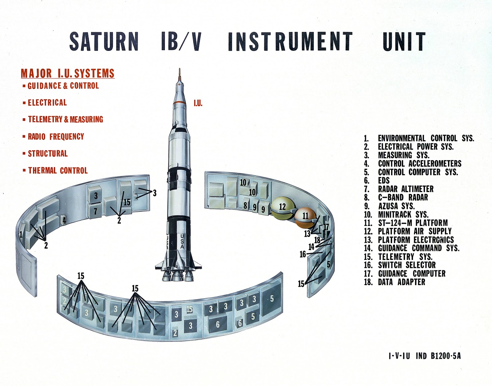
Technicians assemble an Instrument Unit (IU) at the IBM plant in Huntsville, Alabama. In their study, the Douglas/IBM team assumed that the interior walls and portions of the central area of the IU might be used to house new LASS vehicle systems. Image credit: NASA.
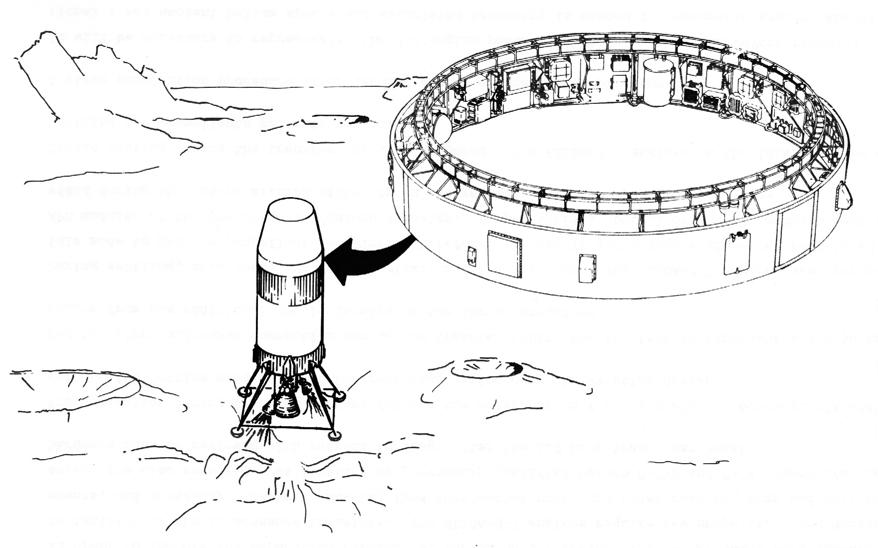
The LASS vehicle just before touchdown on the lunar surface. The illustration displays the position of the IU and, above it, the tapered LASS vehicle payload volume. Image credit: Douglas Aircraft Company/IBM.

The Douglas/IBM team considered the IU to be a candidate location for many new LASS vehicle systems. New navigation and communications systems, for example, would include long-range and short-range lunar landing radars, an altimeter, sensors for tracking the Sun, Earth, stars, and the lunar horizon, a data transmission system including a steerable high-gain dish antenna mounted on the outside of the IU, and a system for homing in on a pre-landed radio beacon at the target landing site on the Moon.  

Though the IU would include new navigational systems, it would still rely heavily on navigational data transmitted from Earth. The Douglas/IBM team expected that reliance on Earth-provided data — which would be generated using inputs from both Earth-based tracking and IU sensors — would ensure that the LASS vehicle could navigate successfully using 1966 state-of-the-art technology. Avoidance of new navigational systems would help to control LASS vehicle development cost.

The IU would also offer a candidate location for electricity-generating systems. These would include three Apollo CSM-type fuel cells, their thermal radiator, and tanks containing their LH2/LOX reactants, as well as rechargeable silver-zinc batteries for handling peak electrical demands during course corrections and the lunar landing burn. The fuel cells would provide three kilowatts of power continuously for the duration of the 110-hour LASS vehicle flight; the batteries would support peak loads of up to 6.76 kilowatts. 

Between 10 and 20 hours after launch, the LASS vehicle would perform its first course correction maneuver. The IU would orient the LASS vehicle for the burn using the APS thrusters, then would pressurize the LH2 tank and J-2 engine using helium drawn from spherical "bottles" mounted on the inner walls of the LH2 tank and on the thrust structure supporting the J-2 and RL-10 engines. 

The RL-10s, which could be ignited without propellant settling, would burn in "10% idle mode" to settle propellants so that they could reach the J-2 engine, then would throttle up as the J-2 ignited. After the three engines fired for a predetermined period of time, they would shut down and the IU would orient the LASS vehicle so that they would again point toward the Sun. If data supplied from Earth indicated that it was necessary, a second course correction would take place between 60 and 100 hours into the flight.

Unlike the Apollo CSM and LM spacecraft, the LASS vehicle would not inject into lunar orbit before descent to its target landing site. Instead, about 15,000 miles (24,140 kilometers) from the Moon and roughly 107 hours after liftoff, the Terminal Landing Phase (TLP) would commence. The IU would reorient the LASS vehicle so that its engines and four landing leg footpads pointed toward the Moon. At TLP start, LASS vehicle mass would total 117,500 pounds (53,300 kilograms).

About two hours later, at an altitude of about 450 miles above the Moon, the lunar horizon sensor would confirm LASS vehicle orientation. At an altitude of 350 miles, the IU would lock onto the signal from the pre-landed beacon at the landing site. The IU computer would begin performing TLP tracking calculations once per second. 

The RL-10 and J-2 engines would ignite to begin TLP Phase I braking at an altitude of 350,000 feet (160,680 meters). At 40,000 feet (12,190 meters), the altimeter would begin to supply data to the IU computer, supplementing beacon tracking data. 

TLP Phase II braking would begin with J-2 shutdown at 25,000 feet (7620 meters). At 10,000 feet (3050 meters), the IU would cease homing on the beacon. The IU computer would then very sensibly seek, as the Douglas/IBM team put it, to "drive all velocities relative to the surface to zero."

LASS vehicle landing legs and footpads. Image credit: Douglas Aircraft Company/IBM.

The IU would throttle the RL-10 engines to maintain a vertical descent velocity of 10 feet (three meters) per second and a lateral velocity of less than three feet (one meter) per second. When the IU-mounted short-range landing radar indicated an altitude of 70 feet (21.3 meters) above the Moon, the LASS vehicle's footpads would be about 10 feet (three meters) from the surface. The IU would then shut down the RL-10s and the LASS vehicle would drop the remaining distance. 

The Douglas/IBM team judged that their TLP system could enable a touchdown within 500 feet (150 meters) of the pre-landed beacon. LASS vehicle mass at touchdown would total 63,580 pounds (28,840 kilograms). Of this, payload above the IU would total up to 27,300 pounds (12,380 kilograms). 

Immediately after touchdown, the IU would command the LASS vehicle to "passivate" itself. The Douglas/IBM team did not describe the passivation process in any detail, though its aim would be to evacuate vessels containing liquids and gases that might freeze, leak, or over-pressurize and burst their containers. For example, about 2000 pounds (910 kilograms) of leftover LH2 and LOX propellants in the LASS vehicle tanks would be vented overboard. Gases and liquids in the payload would, of course, be immune from passivation.

After an unspecified period of time, astronauts would land near the LASS vehicle in an Apollo LM. The Douglas/IBM team provided few details about how the crew would interact with the LASS vehicle. They offered only a few vague suggestions concerning, for example, how astronauts in bulky space suits might ascend the approximately 60 feet (18.3 meters) to the top of the LASS vehicle to reach the payload. Neither did they describe how payload items would be moved from the top of the LASS vehicle to the surface, though they suggested that unspecified "cargo & handling equipment" with a mass of 3100 pounds (1400 kilograms) would be available. These and other mysteries would no doubt have been addressed if NASA had opted to fund additional LASS studies.

The Douglas/IBM engineers did, however, define five typical LASS payload configurations and mission durations. All would feature lunar exploration hardware under consideration in 1966 for AAP lunar missions and would see IU navigational and communications electronics serve double-duty as experiment data support equipment.

Configuration 1 was most in keeping with the role of the LASS vehicle as a sequel to an S-IVB-derived laboratory in low-Earth orbit. The LASS vehicle's LH2 tank would be lined with 3940 pounds (1785 kilograms) of micrometeoroid shielding and thermal insulation before launch from Earth; this weight would be subtracted from the weight available for payload above the IU. 

About 7700 pounds (3490 kilograms) of the payload above the IU would take the form of a two-man shelter similar to the SSESM proposed for the Earth-orbiting S-IVB laboratory. Life support gases and liquids and other expendables would account for 4500 pounds (2040 kilograms) of the payload. Experiment apparatus with a total weight of 500 pounds (227 kilograms), a 1000-pound (454-kilogram) unpressurized Lunar Scientific Survey Module (LSSM) rover, and a one-or-two-person Lunar Flying Unit (LFU) of unspecified weight would make up the balance of the payload.

LASS vehicle candidate lunar surface payload: Lunar Scientific Survey Module (LSSM) rover. Image credit: NASA.
LASS vehicle candidate lunar surface payload: Lunar Flying Unit. Image credit; Bell Aerospace.

Configuration 1 would see the two astronauts lower themselves into the LASS vehicle LH2 tank by unspecified means through an airlock in the shelter. The LH2 tank would then serve as either a laboratory or an emergency shelter. The crew would live in the LASS vehicle for up to 14 days before they reactivated their LM and returned to the Apollo CSM waiting in lunar orbit.

The other four LASS payload configurations would not make use of the LH2 tank, so the weight of the shielding and insulation surrounding it in Configuration 1 could be applied to payload above the IU. Configuration 2, with a 30-day lunar surface stay time, would include a 13,000-pound (5900-kilogram) four-man shelter, a 3800-pound (1725-kilogram) small (though possibly pressurized) rover, 4500 pounds (2040 kilograms) of science equipment, and 5700 pounds (2585 kilograms) of expendables. The Douglas/IBM team did not explain how four astronauts could reach the LASS vehicle on the Moon using the three-man CSM and two-man LM. 

Configuration 3 would include a four-man shelter, an LSSM, science equipment, and 8500 pounds (3855 kilograms) of expendables. The four-person crew would remain on the Moon for 59 days. Configuration 4 would include a two-person shelter, a small rover, scientific equipment, and 11,000 pounds (4990 kilograms) of expendables. The crew would evenly divide their time during their 120-day lunar surface stay between the shelter and the small rover. Configuration 5 would include a two-person shelter, an LSSM, scientific equipment, and 13,800 pounds (6260 kilograms) of expendables. The crew would evenly divide their time during their 195-day stay between the shelter and the LSSM. 

The Douglas/IBM team suggested that the astronauts might tip the roughly 60,000-pound (27,215-kilogram) LASS vehicle on its side to place its payload above the IU — which in this case would not include a shelter — close to the lunar surface. They did not, however, explain how the astronauts might accomplish this feat. They suggested that the crew could live inside their LM while they unloaded equipment from the tipped LASS vehicle and converted its LH2 tank into a shelter. 

A LASS vehicle with more extensive modifications — for example, a large rectangular hole cut into its LH2 tank for mounting a telescope — might be tipped on its side and converted into a lunar surface astronomical observatory. Ultimately, multiple upright and tipped LASS vehicles might be dragged together to form a "LASS Modular Lunar Base." The Douglas/IBM engineers ended their report by declaring that "LASS is envisioned to be the vehicle to support all lunar surface programs." 

During the 1960s, Douglas, IBM, and other contractors studied other new roles for the S-IVB and IU. These included a lunar-orbital lab, a testbed for reusable single-stage-to-orbit vehicles, a communications relay supporting missions to the Moon's farside hemisphere, a delivery vehicle for multiple automated lunar landers based on the Apollo LM descent stage, a testbed for interplanetary heat shield tests, and an interplanetary booster for automated and piloted spacecraft. Some of these are described in the "More Information" section below. Others will be described in future posts.

Sources

"NASA Launch Vehicles," Aviation Week & Space Technology, 2 July 1962, p. 91.

"Rendezvous to Slash Apollo Target Time," Aviation Week & Space Technology, 2 July 1962, pp. 106-111.

"Marshall Supervises Booster Development," Aviation Week & Space Technology, 2 July 1962, pp. 113-125.

Lunar Orbit Rendezvous — News Conference on Apollo Plans at NASA Headquarters on July 11, 1962, News Release and Press Conference Transcript, NASA, 1962.

Lunar Applications of a Spent S-IVB/IU Stage (LASS), presentation by Douglas Aircraft Company Missile & Space Systems Division and International Business Machines Federal Systems Division, September 1966.

"NASA Adapting S-4B for Space Station," W. Normyle, Aviation Week & Space Technology, 5 September 1966, p. 34.

"Manned Lunar Program Options Mission Modes," TM-67-1012-5, C. Bendersky & D. R. Valley, Bellcomm, Inc., 5 May 1967, pp. 9-10.

"Lunar Applications of a Spent S-IVB/IU Stage (LASS)," Douglas Paper No. 4256, L. O. Schulte & D. E. Davin, Douglas Missile & Space Systems Division; paper presented at the American Institute of Aeronautics and Astronautics Fourth Annual Meeting and Technical Display in Anaheim, California, 23-27 October 1967.

Stages to Saturn: A Technological History of the Apollo/Saturn, NASA SP-4206, Roger Bilstein, 1980, pp. 58-85, 129-153, 157-190, 241-257, 323-329, 336-345, 414-415.

More Information

One-Man Space Station (1960)

Space Station Gemini (1962)

Space Station Resupply: A 1963 Plan to Turn the Apollo Spacecraft Into a Space Freighter

Re-Purposing Mercury: Recoverable Space Observatory (1964)

"Still Under Active Consideration": Five Proposed Earth-Orbital Apollo Missions for the 1970s (1971)

Evolution vs. Revolution: The 1970s Battle for NASA's Future

Talking to the Farside: A 1963 Proposal to Use the Apollo Saturn V S-IVB Stage as a Radio Relay

Relighting the FIRE: A 1966 Proposal for Piloted Interplanetary Mission Reentry Tests

NASA's Planetary Joint Action Group Piloted Mars Flyby Study (1966)

"Without Hiatus": The Apollo Applications Program in June 1966

The First Voyager (1967)